Rakesh Suresh
Well-known member
- Joined
- Sep 5, 2024
- Messages
- 110
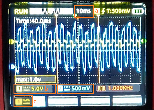
I tested with 100Hz, with ne555
At highest temp: https://1drv.ms/v/s!AoMSicNQxi7y5l0rurHTAl7w-iqS
At lowest temp: https://1drv.ms/v/s!AoMSicNQxi7y5l6Xvp-w6h47uPL4
No change in aluminum temp even after 5 mins of it running.
At highest temp: https://1drv.ms/v/s!AoMSicNQxi7y5l0rurHTAl7w-iqS
At lowest temp: https://1drv.ms/v/s!AoMSicNQxi7y5l6Xvp-w6h47uPL4
No change in aluminum temp even after 5 mins of it running.


")