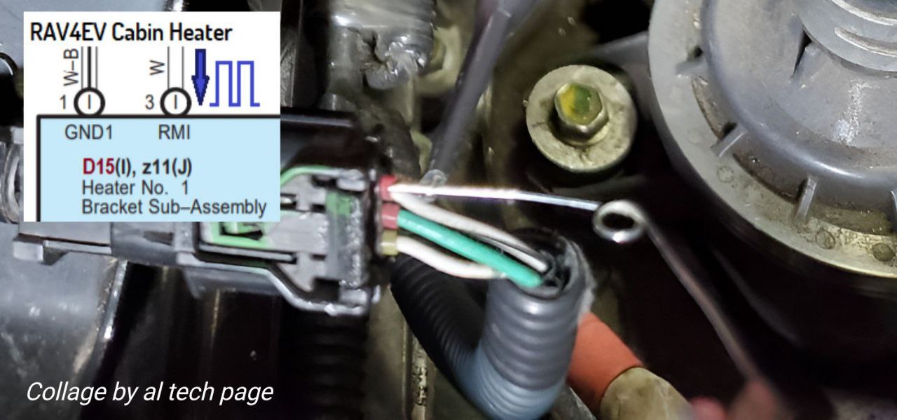
I apologize for the ambiguity.Aargh, sorry about the confusion and frustration caused to you. I thought the bottom right of https://alflash.com.ua/2019/to_rav4ev/cab_heat_w.png is D15. I will repeat the test properly soon. The screenshot above helped.
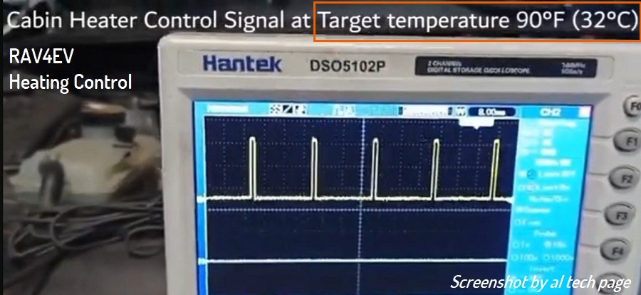
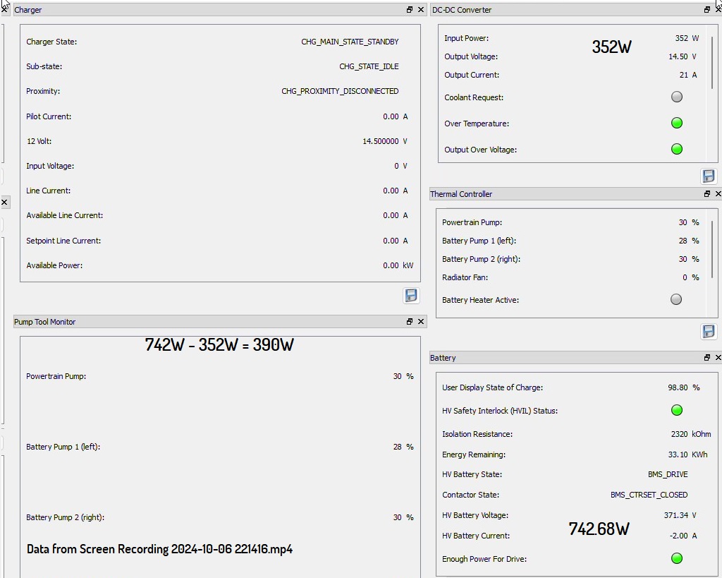
In the screen recording of TPD, the temp was at "HI". Ambient temp was at 64 degrees F, but the compressor was running every 10 seconds or so.
I corrected it as best I could
Update.
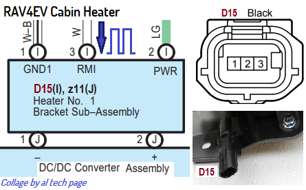
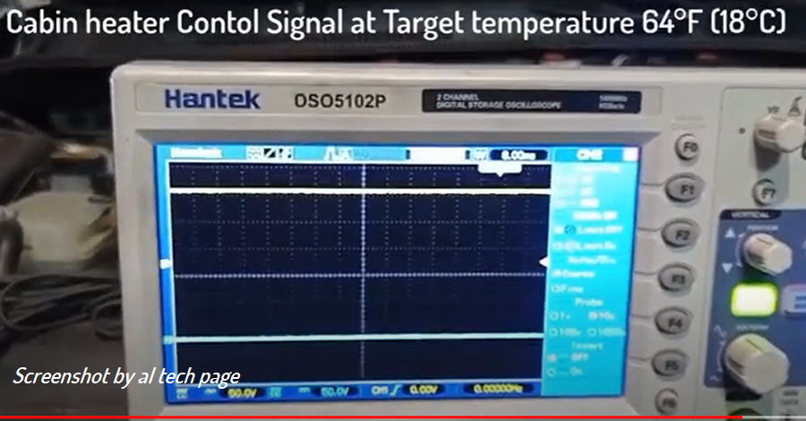
https://alflash.com.ua/2019/to_rav4ev/cab_heat_w2.png
I don't know if RAV4EV has AC drying mode.
Last edited:


")