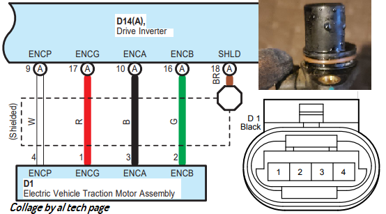
1. This picture (https://alflash.com.ua/2019/to_rav4ev/cab_heat_w2.png) is only a compilation of images taken from the repair manual of this car. Perhaps you are confusing the "male" and "female" connectors or the front and back sides of the connector.... Yes, the pin is on the wire with a black stripe. I double checked pin 3 (RMI) in this https://alflash.com.ua/2019/to_rav4ev/cab_heat_w2.png Does the top right have GND and RMI flipped, or am I reading it wrong? So, I will to place the pin on the white wire and test at 3 diff temp settings.
But in all cases, the color marking of the wiring allows you to clearly determine the purpose of the contacts.
2. I don't understand how heat can enter the cabin if there is no heat carrier between the heat sources (heater) and heat receivers (cabin heat exchanger)...
3. Have you checked the accuracy of the Chinese "thermometer"?
Why should it show exactly the same temperature as the Toyota sensor?
Have you set the surface reflection coefficient for your infrared thermometer?
4. I believe that by monitoring the current from the high-voltage battery, you can turn on the cabin heater briefly (for tens of seconds) and with a pause for cooling.
Earlier in my video* I showed the heating of the heater radiator to >134°C (>270°F). After which the heating element remained serviceable.
By the way, has the A/C performance been checked?
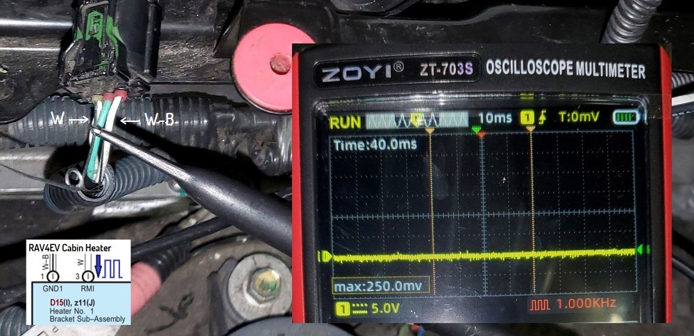
I hope to see a photo of the control signal of the cabin heater of this RAV4EV.
* The actual data (dependence of the current through the element on the temperature at constant voltage) in this video proved that this cabin heater does not PTC element is used.
https://alflash.com.ua/2019/to_rav4ev/ptc.jpg
")
Last edited: