Thanks for the clarification.See post #6.
My question was to check if any other codes had popped up during your test drive.


Thanks for the clarification.See post #6.
Questions. Can you make and publish voltage oscillograms on the contacts of the motor speed sensor with the rotor stationary and when it rotates (before and after replacing it)?I'll replace the speed sensor, clear all the clearable Alerts (DTCs), then generate a fresh batch if problems persist.


 . Thanks, octopart.
Date | Description | Amount | Vendor | Notes |
15Aug2024 | SENSOR ENCODER 1002722-00-x, (2) @ $15.78; 2.84 tax | 43.40 | via eBay | |
| Housing, Plug, TE/AMP 444046-4 (“-4” comes with green housing seal, no terminals or wire seals). $3.96 ea. but MOQ of (5) = $19.80; $8.99 UPS; $1.29 tax. Update: was charged another 0.49 for unknown reason. | 30.57 | OnlineComponents.com | |
| Terminal, Receptacle (female), TE/AMP 282438-1, 17-20 AWG. $0.13 ea. but MOQ = (100) = $13.00. Shipping = $9.99. Tax = $2.07. From UK. | 25.06 | Newark.com | |
| Wire Seal, TE/AMP 963531-1, for wire OD .074”, Gray. $0.104 each, (20) = $2.08. Shipping - $12.90 | 14.98 | TME.eu | |
20ug2026 | Terminal, Tab (male), TE/AMP 282440-1, (50), 17-20 AWG. $.238 ea. = 11.90; shipping = 7.99; tax = 1.79 | 21.68 | Mouser.com | (ref: https://www.te.com/en/product-282440-1.html) |
| | | | |
| Total | $135.69 | for materials to build (5) breakout harnesses. | |
Maybe part of the story, but not the whole story. I found it was easiest to trigger the Check EV issue after the car had been sitting for a while. On my first investigative run, the Check EV message came up after about 3/4 mile, then it took probably no more than 30 seconds of sitting turned off for it to be drivable, I drove the car around the block for ~10 miles without the problem reoccurring. At that point I parked the car and left it sit for ~2 hours. Then it again took about 3/4 mile for the Check EV to reappear. However this time it reoccurred while driving the 1/4 mile home. It also seems to mostly occur when braking, and usually in the last little part of coming to a stop.The sensor "seems" to warm up and malfunction, based on the requirement to leave the system OFF for two+ minutes before a successful drive can occur.


Will the measurement tool be a regular/generic DVOM with a measuring bridge voltage of 5÷9 volts or a megohmmeter with a test voltage of 500÷1000 volts?
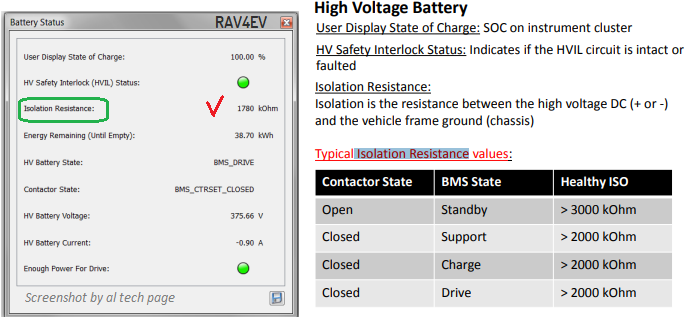
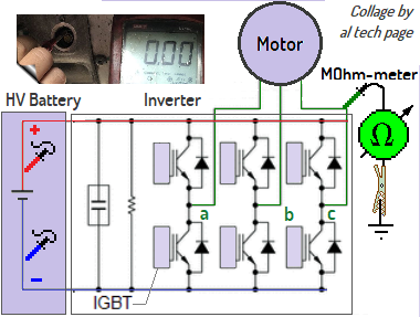
As I understand, violations of the insulation resistance between the stator and its housing are detected by the inverter.
And in the event of an unacceptable violation of this insulation, the inverter stops supplying alternating voltage to the stator windings and notifies the system about this with a Faulty signal.
And as a result, the BMS switches the contactors to the Open state.


As far as I understand, there (https://www.myrav4ev.com/threads/fs-2012-rav4-sf-south-bay-san-jose-area.2660/#post-31368) describes checking the insulation resistance between high voltage DC* (+ or -) and GND.I used a Fluke 1507 Insulation Tester, set for 500v testing, and I obtained a steady 4Mohm (manual test, holding the 'Test' button for as long as I like).
Except . . . not always, according to Matt's testing.
---
Not mine. I am usually good about making sure no tools are left behind. I have a screwdriver that looks similar but I just checked and mine is in the toolbox. Never owned a Stanley socket.I found a couple of tools . . . are these yours, Richard? I can mail them back to you.


Please, any updates on the cause of this code?Checked Tesla side via TPD: no Alerts (new or historical).
Firmware is at 1.3.101
Installed the new Toyota-sourced speed sensor. Old sensor was dry.
As soon as I put it in 'R' and pressed the accel, "Check EV".
Left system on, checked TPD: DI_f020
View attachment 658
The contactors remained closed, until I turned off the vehicle.