


The fact that the heating elements of this heater are not PTC type is not a limitation for their testing without cooling the radiator with a circulating flow of liquid.
My experiments with them (video in https://www.myrav4ev.com/threads/charging-stopped-due-to-system-malfunction.2692/post-31974) showed that even when the radiator was heated to a temperature of >265°F and only one element, this element remained both electrically and externally completely serviceable.
The severity of the consequences for the pump of it running "dry" is unknown to me. But I assume that they can't remain without consequences as minimum in the long term...
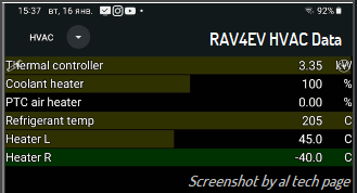
Note. HVAC system have DTC about water temperature sensor
Therefore, this can be an indirect check of the heater temperature.
Although there are multiple cases of cabin heater failure due to a shorted IGBT and, as a consequence, faulty elements of its group.
If replacement is impossible, repair often consists of simply disconnecting the faulty group from the HV power supply.
This reduces the range of temperature adjustment options, but does not deprive the possibility of heating the cabin.
My experiments with them (video in https://www.myrav4ev.com/threads/charging-stopped-due-to-system-malfunction.2692/post-31974) showed that even when the radiator was heated to a temperature of >265°F and only one element, this element remained both electrically and externally completely serviceable.
The severity of the consequences for the pump of it running "dry" is unknown to me. But I assume that they can't remain without consequences as minimum in the long term...
Note. HVAC system have DTC about water temperature sensor
Therefore, this can be an indirect check of the heater temperature.
Although there are multiple cases of cabin heater failure due to a shorted IGBT and, as a consequence, faulty elements of its group.
If replacement is impossible, repair often consists of simply disconnecting the faulty group from the HV power supply.
This reduces the range of temperature adjustment options, but does not deprive the possibility of heating the cabin.


")