Charging stopped due to system malfunction

Toyota Rav4 EV Forum

Help Support Toyota Rav4 EV Forum:

This site may earn a commission from merchant affiliate links, including eBay, Amazon, and others.
... Also I am unable to get the ne555 to output 40hz. It jumps from like 10hz to 100hz in the second jumper setting. Is 100hz ok?
I can't answer your question, because I haven't checked the possibility of variations in the heater control signal frequency. But I think that a change of 2 times in either direction is not acceptable.
It is possible that the cause of the malfunction is that for a frequency of 40 Hz the regulator is in the extreme position.
Try changing/increasing the capacity of the time-setting capacitor C1. Perhaps changing the duty cycle will help.

UPD. 45 caliber cartridge will not fit into a 38 caliber weapon, much less a 32 caliber...
 
Last edited:
... At lowest temp: https://1drv.ms/v/s!AoMSicNQxi7y5l6Xvp-w6h47uPL4

No change in aluminum temp even after 5 mins of it running.
Strange situation. On one hand, there is no adequate heater control signal from the Power Management ECU, and on the other hand, the heater is not activated under "manual control" from simulator.

Just in case, I will ask, is the cabin heater power fuse still intact/serviceable?

It is possible that we are missing a necessary check or are mistaken in one of the previously performed...

p.s. Is this (attach.) the signal that is fed to the RMI input of the cabin heater and at the same time both 12V and GND are fed into it?
 

Attachments

  • Screenshot_20241015_001100_OneDrive.jpg
    Screenshot_20241015_001100_OneDrive.jpg
    102.2 KB
Last edited:
Just in case, I will ask, is the cabin heater power fuse still intact/serviceable?
You the continuity check between HV terminals on DC-DC and cabin terminals. I checked. If a fuse were to be blown we would expect the voltage at the cabin heater hv terminals to be zero correct?


p.s. Is this (attach.) the signal that is fed to the RMI input of the cabin heater and at the same time both 12V and GND are fed into it?
Yes, all 3 are fed using the replacement connector I made in the order gnd, rmi and pwr.
 
Got a good video of it. https://1drv.ms/v/s!AoMSicNQxi7y5l-3pQCOwc1stk4l

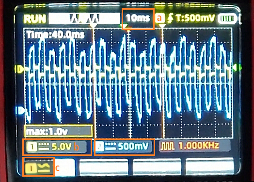
Channel 1 connected to pin 2 from top
Channel 2 connected to pin 4 from top
View attachment 991
Checking the engine speed sensor with an oscilloscope.

Thank you for your attention to my request!
Your video is a great help to many RAV4EV owners.

1. Please report the conditions/state/mode under which the speed sensor signals had the shape shown in the video.
Ign ON/READY ?​
Transmission selector P/N/D/R ?​
Brake pedal Released/Pressed ?​
Accelerator pedal Released/Pressed ?​


2. My partial/incomplete guesses.
Stage 1. Only IGN On.​
Stage 2. Go to READY.​
Stage 3. Stator RPM <1.​
Stage 4. Stator RPM>7.​
I don't want to guess at what exact state the rotor started moving :) :)
 
Last edited:
Ign ON/READY ?Transmission selector P/N/D/R ?Brake pedal Released/Pressed ?Accelerator pedal Released/Pressed ?

Stage 1: Car was OFF
Stage 2: Press IGN on to READY directly, with foot on brake, transmission set to D
Stage 3: Brake slightly released
Stage 4: READY, D, Brake fully released but accelerator not pressed (tires were coasting). (Green ECO light was ON)
 
Stage 1: Car was OFF
Stage 2: Press IGN on to READY directly, with foot on brake, transmission set to D
Stage 3: Brake slightly released
Stage 4: READY, D, Brake fully released but accelerator not pressed (tires were coasting). (Green ECO light was ON)
Thanks for clarification!

Judging by the way the pulse repetition period changes in state 3, it is quite likely that the rotor is already rotating in this state.
Recommendations regarding this case of using an oscilloscope.
a) reduce the sweep time to 5 ms per division;​
b) set the sensitivity to 1 V per division for both channels;​
c) (optional) since one of the outputs has a constant component (approximately >2 V), then "close" the input so that the oscilloscope displays alternating signals (the icon of this mode is in an orange outline).​

My confusion.* I cannot understand why the signals are so different in shape. One of them resembles the output signal of an inductive sensor (pseudo sine wave), and the other is similar to the output of a digital sensor (rectangle).
https://alflash.com.ua/2019/to_rav4ev/speed_s1.png
speed_s1.png


It's a pity that the oscilloscope is not protected from interference with a frequency of 100 Hz.
What is your AC frequency, 50 Hz or 60 Hz?

* UPD. Apparently this drawing removes almost all questions about the forms of signals of the rotor rotation sensor :)
Thanks to this post, https://www.myrav4ev.com/threads/speed-sensor-check-for-fluid.2667/#post-32025 , we may already know the internal structure of this sensor.
*
https://alflash.com.ua/2019/to_rav4ev/enc.jpg
https://alflash.com.ua/2019/to_rav4ev/enc1.jpg
 
Last edited:
Got a good video of it. https://1drv.ms/v/s!AoMSicNQxi7y5l-3pQCOwc1stk4l

Channel 1 connected to pin 2 from top
Channel 2 connected to pin 4 from top
View attachment 991
p.s.s. Unfortunately, this question only came up now... :(
According to RAVEV RM, the rotor speed sensor is connected as shown in this image
https://alflash.com.ua/2019/to_rav4ev/w_sp_sens.png
And pin 4 (white wire) is the sensor supply voltage.
Is this true or am I wrong?
https://alflash.com.ua/2019/to_rav4ev/encoder.png
encoder.png
 
Last edited:
And pin 4 (white wire) is the sensor supply voltage.

I will get the speed sensor video again slowly this time, with changes to oscilloscope settings. We can see how the 2 behave. Forgot to mention, Pin 3 always had zero voltage when I tested.
 
I will get the speed sensor video again slowly this time, with changes to oscilloscope settings. We can see how the 2 behave. Forgot to mention, Pin 3 always had zero voltage when I tested.
And again my questions, recommendations and requests :)
1. Why is there no sensor supply voltage on the oscillogram of contact No.4? This is nonsense.​
2. Connect the common wire of the oscilloscope to the motor housing.​
3. Check/measure the signals on all four contacts and show the results with Ready, with D and with D and both pedals not pressed.​
4. Show the result of checking the signals on contacts #2 and #3 with the oscilloscope in states 2, 3 and 4. Please, voice the moment of transition to these states and the moment when the wheels start to rotate.​
5. Be sure to check the reliability of the connection of the oscilloscope probes.
 
Last edited:
Why is there no sensor supply voltage on the oscillogram of contact No.4? This is nonsense.
I meant Pin #3, ENCA, as you had annotated in the pic above had zero voltage in all states. However, I have not tested in reverse.
Connect the common wire of the oscilloscope to the motor housing.3. Check/measure the signals on all four contacts and show the results with Ready, with D and with D and both pedals not pressed.4. Show the result of checking the signals on contacts #2 and #3 with the oscilloscope in states 2, 3 and 4. Please, voice the moment of transition to these states and the moment when the wheels start to rotate.5. Be sure to check the reliability of the connection of the oscilloscope probes.
Understood.
 
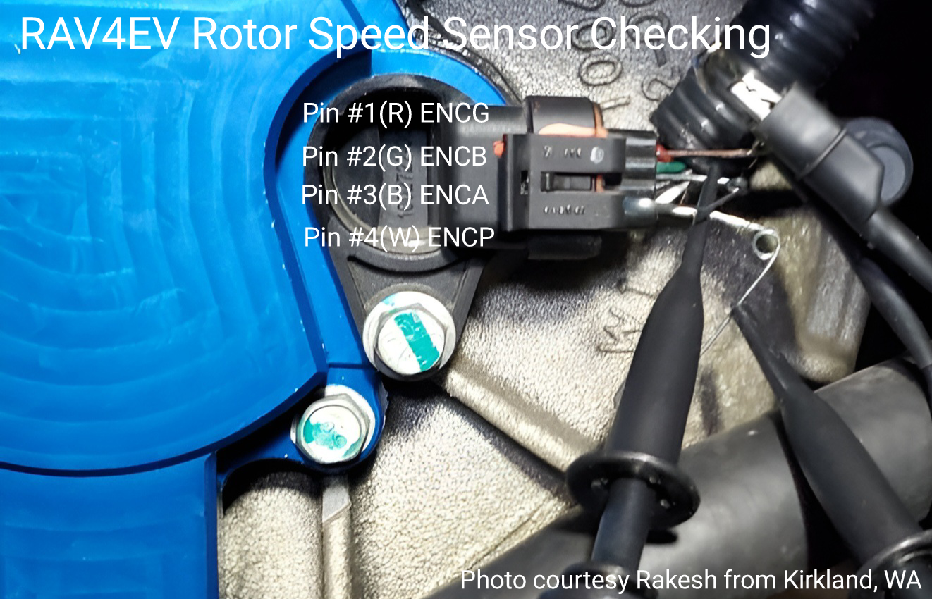
Sorry, but that photo shows the connection to pins #1, #2 and #4 (to the red, green and white wires).
Correct, but I did test by connecting probes to 2, 3 where 3 was always 0V. I then switched to 2 and 4 which showed interesting waveforms and that is the video I shared. I can record and share a video of probe on pin 3 as well.
 
Correct, but I did test by connecting probes to 2, 3 where 3 was always 0V. I then switched to 2 and 4 which showed interesting waveforms and that is the video I shared. I can record and share a video of probe on pin 3 as well.
There should be supply voltage on pin #4, but the oscilloscope only shows interference.
Sir, the sensor CAN'T work without power.
 
2. Connect the common wire of the oscilloscope to the motor housing.3. Check/measure the signals on all four contacts and show the results with Ready, with D and with D and both pedals not pressed.4. Show the result of checking the signals on contacts #2 and #3 with the oscilloscope in states 2, 3 and 4. Please, voice the moment of transition to these states and the moment when the wheels start to rotate.5. Be sure to check the reliability of the connection of the oscilloscope probes.

Probe 1: ENCB
Probe 2: ENCA
20241017_194935.jpg

Video of oscilloscope - https://1drv.ms/v/s!AoMSicNQxi7y5nhRkT3iP-2dlaKr
Video of speed - https://1drv.ms/v/c/a645fc7be4ec742f/Ef09MzDYFiRNsZYAKSHdDgMBNvKdbNTEmekGD7fH_0lGKQ?e=zocds8

Steps in video:
  1. IGN on, no READY
  2. READY
  3. D, with brake pressed
  4. Brake partially released
  5. Brake fully released (no pedal pressed)

It appears connecting to motor housing removed interference.
 
Last edited:

Probe 1: ENCB
Probe 2: ENCA
View attachment 1018

Video of oscilloscope - https://1drv.ms/v/s!AoMSicNQxi7y5nhRkT3iP-2dlaKr
Video of speed - https://1drv.ms/v/c/a645fc7be4ec742f/Ef09MzDYFiRNsZYAKSHdDgMBNvKdbNTEmekGD7fH_0lGKQ?e=zocds8
Steps in video:
  1. IGN on, no READY
  2. READY
  3. D, with brake pressed
  4. Brake partially released
  5. Brake fully released (no pedal pressed)
It appears connecting to motor housing removed interference.
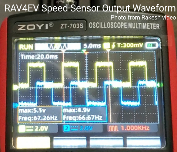
Wow! Classic example (attach.1) two-channel incremental waveform encoder*.
Good result, thanks!
*https://www.haydonkerkpittman.com/learningzone/whitepapers/incremental-encoder-signals
As I understand osc. data during this shot, the rotor speed was approximately 112 rpm.
https://alflash.com.ua/2019/to_rav4ev/enc_data.png
enc_data.png


Full off-topic.
This photo (attach.2) shows how AI understands/sees this check :)
https://alflash.com.ua/2019/to_rav4ev/osc_ch.png
 
Last edited:
Probe 1: ENCB
Probe 2: ENCA
View attachment 1018

Video of oscilloscope - https://1drv.ms/v/s!AoMSicNQxi7y5nhRkT3iP-2dlaKr
Video of speed - https://1drv.ms/v/c/a645fc7be4ec742f/Ef09MzDYFiRNsZYAKSHdDgMBNvKdbNTEmekGD7fH_0lGKQ?e=zocds8

Steps in video:
  1. IGN on, no READY
  2. READY
  3. D, with brake pressed
  4. Brake partially released
  5. Brake fully released (no pedal pressed)

It appears connecting to motor housing removed interference.
Video about this yours checking (...//youtu.be/up744uu-lcs)


Thanks for photos and video!


p.s. Extraneous sound at the end of the video against the background of the Proximity sound, appears with the same repetition frequency ... :(
 
Last edited:
Back
Top