Charging stopped due to system malfunction

Toyota Rav4 EV Forum

Help Support Toyota Rav4 EV Forum:

This site may earn a commission from merchant affiliate links, including eBay, Amazon, and others.
Funny thing happened. While connecting the probes, the pins touching ENCA and ENCB got shorted and I got check ev system light and wheels did not move. I guess this is expected?
 
@alflash Irrelevant question for this forum, but a quick one. What tools you use to create these videos that you post on Youtube :)

Now that we have wrapped up the speed sensor testing, I have a few questions about what more could be done to diagnose the heater issue.
1. I think the only test I am yet to do is test with exactly at 40Hz PWM. (I have tested at 4Hz and 100Hz). Is it really necessary to have a 50% duty cycle pwm? if 100% duty cycle is a valid state, could tying RMI to ground a valid test?
2. Can I connect probes to components on the PCB for further testing? We would expect the IGBTs to output HV PWM correct? Would connecting a lead to IGBT terminal and HV negative a useful test to do?
3. There seems to be a Hall effect current sensor where I can connect leads to. Would that help at all?
4. In your image it appears that the peak voltage of PWM of heater control signal is close to 12V. Any other tests I could do to investigate why my heater control signal has a very small peak voltage?
5. Also immediately preceeding the failure of heater, the GoM had dropped to ~70miles for a few months even when heater was off. However, after the heater stopped working GoM went back to usual ranges. Is there any way to correlate this symptom?
 
Last edited:
@alflash Irrelevant question for this forum, but a quick one. What tools you use to create these videos that you post on Youtube :)
Depending on the list of purposes and goals of creating a video, I use different sets of video editors.For example, Movavi, Clipchamp, Camtasia and several more AI editors and AI generators "text in photo" and "text in video".
As example, this quick and small attach.3. ;)
Now that we have wrapped up the speed sensor testing, I have a few questions about what more could be done to diagnose the heater issue.
I do not consider the verification complete because there are still questions (for example, point 1).
1. I think the only test I am yet to do is test with exactly at 40Hz PWM. (I have tested at 4Hz and 100Hz). Is it really necessary to have a 50% duty cycle pwm? if 100% duty cycle is a valid state, could tying RMI to ground a valid test?
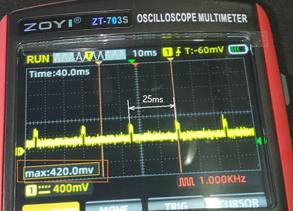
A) In this image (attach.1) we can see that the pulse repetition frequency of the simulator is approximately 40 Hz.​
B) Use any pulse duty cycle in the range from 20% (max T) to 80% min T).​
C) I do not know the result of connecting the RMI input to GND. And I would be satisfied with only checking the heater current (according to the program data) when connecting to it (pin RMI) a pulse signal with different duty cycle values (20 ÷ 80%) of the simulator pulses with a frequency of 40 Hz.​
2. Can I connect probes to components on the PCB for further testing? We would expect the IGBTs to output HV PWM correct? Would connecting a lead to IGBT terminal and HV negative a useful test to do?
Note. The electric control circuits of the heater groups (IGBTs, it drivers, controller, etc.) are galvanically separated/isolated from the input control signal (optocouplers), 12V power supply and GND of vehicle.
And they are powered by HV voltage. I consider it incorrect, inappropriate and dangerous to connect measuring devices to HV lines if the cover of the orange Sevice Grip connector is not removed!
3. There seems to be a Hall effect current sensor where I can connect leads to. Would that help at all?
It is possible to measure the current from the HV battery using the program, there are current clamps that fix the zero point before measuring in the absence of current.
Therefore, I don't see the benefit/necessity of using the HV heater current sensor (attach.2) + note in point 2).
4. In your image it appears that the peak voltage of PWM of heater control signal is close to 12V. Any other tests I could do to investigate why my heater control signal has a very small peak voltage?
I. We are currently examining two features/faults described in your measurement results.
  • Too low/small/"sagged" heater control signal.
  • No heating when attempting to control the heater with the simulator signal.
II. IMO. I believe that one of these tests contains a "methodological error".
III. Therefore, I believe that these tests should be repeated, diversified and supplemented. In particular, supplemented with more intelligible/understandable documentary results describing all the circumstances/conditions/states during these tests. For example, the answer to this question. When testing the heater with the simulator, is +12V, GND and HV Voltage supplied to it (connector D15) (I remember the result of checking the fuse in the DC-DC Converter)? Or is the control signal shape when turning on the heater on the removed wiring connector (D15) also a low level?
5. Also immediately preceeding the failure of heater, the GoM had dropped to ~70miles for a few months even when heater was off. However, after the heater stopped working GoM went back to usual ranges. Is there any way to correlate this symptom?
Probably not.p.

p.s. Have you noticed that at the end of the video, against the background of the "Proximity" sound (https://alflash.com.ua/2019/to_rav4ev/proximity.png), an extraneous "criminal" sound is heard with a period of approximately 0.5 seconds, as well as the rotor speed (about 120 rpm)
 

Attachments

  • IMG_20241019_090139.png
    IMG_20241019_090139.png
    383.7 KB
  • IMG_20241019_094946.png
    IMG_20241019_094946.png
    241.3 KB
  • VID_20241019_112747_193(1) (online-video-cutter.com) (1).mp4
    1.1 MB
Last edited:
In this image (attach.1) we can see that the pulse repetition frequency of the simulator is approximately 40 Hz.B) Use any pulse duty cycle in the range from 20% (max T) to 80% min T).C) I do not know the result of connecting the RMI input to GND. And I would be satisfied with only checking the heater current (according to the program data) when connecting to it (pin RMI) a pulse signal with different duty cycle values (20 ÷ 80%) of the simulator pulses with a frequency of 40 Hz.
I repeated the test with 40Hz and heater got warm !!
(To get to 40khz I had to carefully configure the potentiometers without turning it too far and use the lower part of second jumper setting)

I see intermittent 2-3A draw using the clamp meter. The right part of the Aluminum block took significantly longer to heat up than the left part. Not sure if this is expected.
 

Attachments

  • 20241019_111659.jpg
    20241019_111659.jpg
    2 MB
  • 20241019_111435.mp4
    12.6 MB
  • 20241019_110931.jpg
    20241019_110931.jpg
    1.2 MB
  • 20241019_110916.jpg
    20241019_110916.jpg
    943.1 KB
  • 20241019_110801.jpg
    20241019_110801.jpg
    1.3 MB
I repeated the test with 40Hz and heater got warm !!
(To get to 40khz I had to carefully configure the potentiometers without turning it too far and use the lower part of second jumper setting)

I see intermittent 2-3A draw using the clamp meter. The right part of the Aluminum block took significantly longer to heat up than the left part. Not sure if this is expected.
Excellent!
1. The heater itself is in good working order. Such a relatively simple check could eliminate the work of removing, disassembling and checking the "insides" of the heater :)
2. Depending on the required heating level, different groups of heaters are switched on. And, judging by the duty cycle shown in the photo, a low heating temperature was set. And therefore, 1-2 extreme groups worked.​
3. Current data from TDS about HV Battery Current?​
4. Let's return to this test result.​
contr_bad.jpg

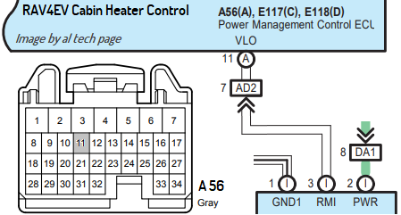
We see only "traces" of the correct control signal: frequency 40 Hz, but the amplitude is a dozen times less.​
Check this signal on the wiring connector without connecting to its counterpart with the cabin heating on.​
Perhaps it will be necessary to deal with the Power Management Control ECU unit.​
It is imperative to reliably double-check whether the pump turns on when the cabin heating is turned on.​

5. There is also relatively good new.​
In case of failure to repair this unit, you can upgrade the system and organize manual control of the heater if the pump turns on. A variable resistor with a switch, instead of the one located on the generator board, should be placed in the cabin and use it to regulate the heating of the cabin.​
But this is a "spare option" and let's try to completely restore this system.​
 
Last edited:
Current data from TDS about HV Battery Current?
I forgot to take a video if it. It was fluctuating between 1-4A. I have disconnected the 555 pwm generator. Would you like to see a photo/video of it?

Check this signal on the wiring connector without connecting to its counterpart with the cabin heating on.
Without connecting d15 - no heater control signal
20241019_163155.jpg

Connecting d15 - weak heater control signal
20241019_165227.jpg


Perhaps it will be necessary to deal with the Power Management Control ECU unit.
Where exactly is this?

It is imperative to reliably double-check whether the pump turns on when the cabin heating is turned on.
How exactly would I know if the pump turns on? I dont hear a continuous buzz like a usual pump, but some intermittent noise is there when heater is turned on.

https://1drv.ms/v/s!AoMSicNQxi7y5kxUESvekQ6Nmm2N - At the 25s mark, we can hear some noise. I have thought that it us the normal cabin heater pump noise. Is that how a cabin heater pump sounds?

Have you noticed that at the end of the video, against the background of the "Proximity" sound
Oh, there was some noise just before the wheels started to move? I had just ignored this noise thinking that it was because the car being jacked up. Is it something to be concerned about? Any thoughts on why it may be happening?

Today is the 7th anniversary of my diagnostics of the first RAV4EV
Wohoo ! Congrats and thanks for all the help !
 
Also, can I close the heater assembly? Do you foresee needing to do any more testing on the heater itself? I wanted to start driving the car.
 
...

Where exactly is this?
...
Wohoo ! Congrats and thanks for all the help !
Thanks :)


1. https://alflash.com.ua/2019/to_rav4ev/pmc.png
pmc.png

https://alflash.com.ua/2019/to_rav4ev/pmc1.jpg
pmc1.jpg


HVAC Part Location https://alflash.com.ua/2019/to_rav4ev/hvac_loc.png
2. Record (under hood) and "show" the noise you are talking about.
A completely reliable, but not the easiest way is to check the pump control signal and the feedback signal with an oscilloscope*.
https://alflash.com.ua/2019/to_rav4ev/hvac_pump.png
hvac_pump.png


Note. The pump works without liquid and probably has a worn out bearing.


Also, can I close the heater assembly? Do you foresee needing to do any more testing on the heater itself? I wanted to start driving the car.
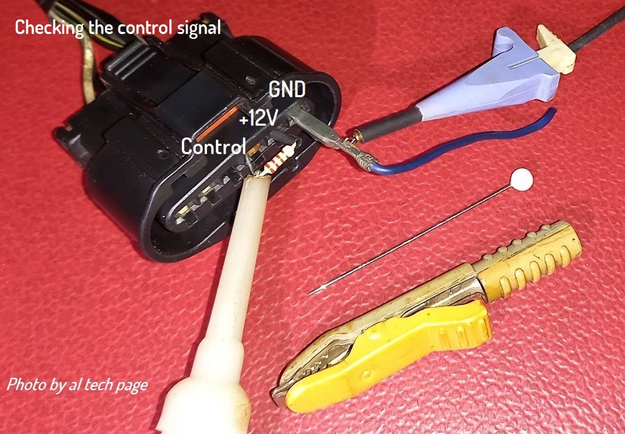
Before this, you need to make sure that the cabin heater is fully functional and is not the cause of very, very small pulses on the RMI contact.

* https://alflash.com.ua/2019/to_rav4ev/connecting1.jpg
connecting1.jpg
 
Last edited:
How exactly would I know if the pump turns on?
Because this pump is so easily accessed, if you can't tell it's running by putting your hand on it and feeling a vibration, you can use a stethoscope (such as this):

1729442412655.png

I use one to hear the battery/drivetrain pumps, because I don't trust the pump speed indicators in TPD. One of those pumps is reasonably easy to put a stethoscope on, but the other isn't. The cabin heater's pump is the easiest of all.
 
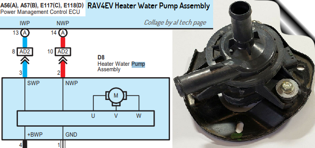
1. TRD does not and cannot have data on the cabin heater pump, since it is part of the Toyota HVAC system*.
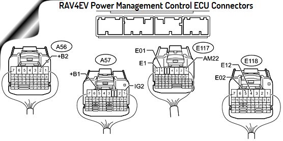
The signals of the cabin heating pump are on pins #13 and #14 of the A56 connector (of Toyota Power management Control ECU).

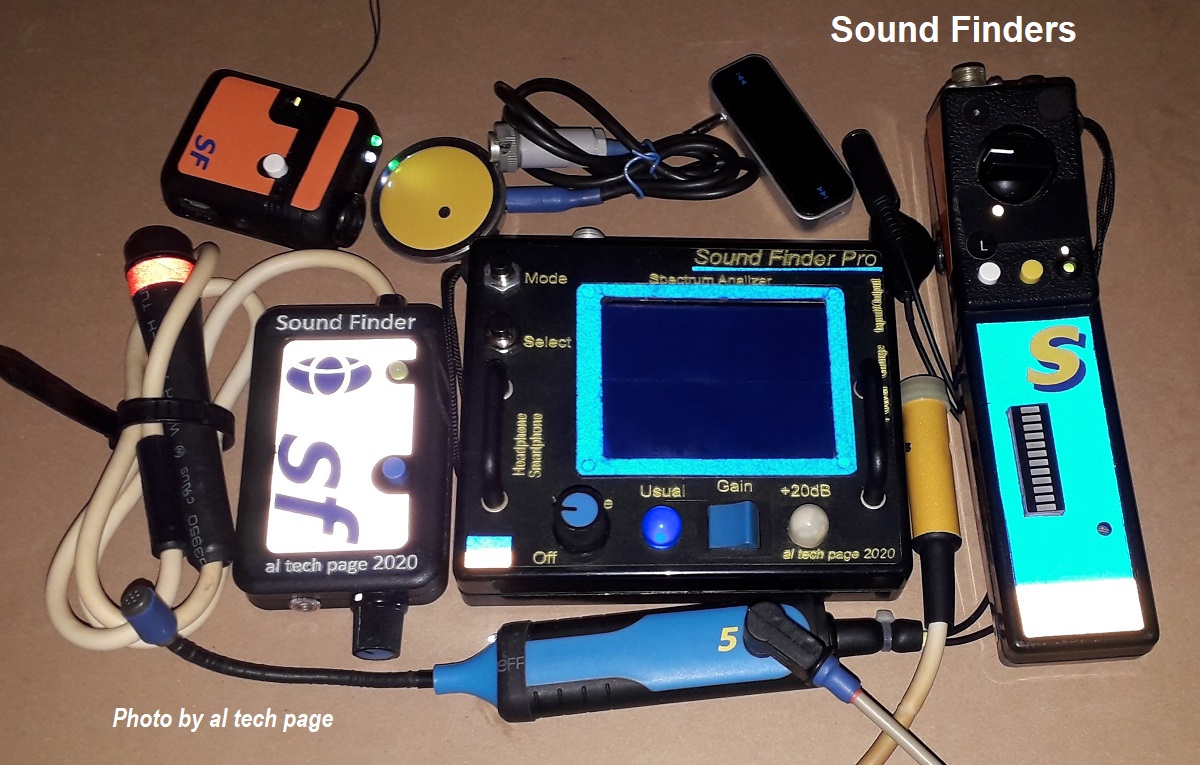
2. Off. To determine the location of the source of extraneous sounds and to record them, I use these homemade devices
https://alflash.com.ua/mydevices/#my_do_it_yourself_devices/20/514_Sound_Finders.jpg
514_Sound_Finders.jpg


https://forum.alflash.com.ua/download/file.php?id=3740
file.php


and spectrum analyzer(s)


Although 30 years ago I started with such a homemade product (an old phonendoscope and antenna from a transistor radio) :)
https://forum.alflash.com.ua/download/file.php?id=2132

* Use Toyota Techstream or Toyota GTS+ software is available this data
  • Electric Water Pump Target Speed (rpm)
  • Electric Water Pump Speed (rpm)
  • Water Pump (On/Off)
And Active test Electric Water Heater (ON or OFF) in Ready Mode.
 
Last edited:
Because this pump is so easily accessed, if you can't tell it's running by putting your hand on it and feeling a vibration, you can use a stethoscope
I definitely hear some repetitive noise but I don't know if that's how a pump functioning normally would sound.
 
In

you can hear the sounds under the hood when all three cooling pumps are forced to turn on.
The cabin heater pump is of the same design. ???
 
Last edited:
I definitely hear some repetitive noise but I don't know if that's how a pump functioning normally would sound.
The sounds are a bit strange, especially the amplitude modulation with a frequency of several hertz. But it seems that the pump is working.

Is there liquid in the system?
The oscillograms are not clear to me. Especially because of their incomprehensible amplitude and the difference in the frequency of their signals...
Apparently this pump is of a different design.
 
Last edited:
The water heater isn't PTC; without liquid, you risk damage to it. It is not intrinsically safe from overheating, as is a PTC heater. Maybe it has overheat protection, but I would not be surprised if it doesn't, or if that protection is in the form of something irreversible.

Most liquid pumps are not rated for operation without liquid. Some pumps' seals can be ruined in seconds when run dry. These pumps don't have friction seals, so that's not an issue for them, but their bearing will probably not appreciate being run dry for any appreciable time!

Tesla_Coolant_Pump_04b.jpg

Given that, I'm not at all surprised at the cyclic frequency I hear in your video of it running.
 
Most liquid pumps are not rated for operation without liquid. Some pumps' seals can be ruined in seconds when run dry. These pumps don't have friction seals, so that's not an issue for them, but their bearing will probably not appreciate being run dry for any appreciable time!
Oops. I must have run it dry cumulatively for over 30 mins to do all the tests.


@alflash Given that there was not a big drop in RMI peak voltage when I used the NE555 pwm generator, could we conclude that the heater is not causing the weak heater control signal?
 
Back
Top