Charging stopped due to system malfunction

Toyota Rav4 EV Forum

Help Support Toyota Rav4 EV Forum:

This site may earn a commission from merchant affiliate links, including eBay, Amazon, and others.
... Yes, the pin is on the wire with a black stripe. I double checked pin 3 (RMI) in this https://alflash.com.ua/2019/to_rav4ev/cab_heat_w2.png Does the top right have GND and RMI flipped, or am I reading it wrong? So, I will to place the pin on the white wire and test at 3 diff temp settings.
1. This picture (https://alflash.com.ua/2019/to_rav4ev/cab_heat_w2.png) is only a compilation of images taken from the repair manual of this car. Perhaps you are confusing the "male" and "female" connectors or the front and back sides of the connector.
But in all cases, the color marking of the wiring allows you to clearly determine the purpose of the contacts.

2. I don't understand how heat can enter the cabin if there is no heat carrier between the heat sources (heater) and heat receivers (cabin heat exchanger)...
3. Have you checked the accuracy of the Chinese "thermometer"?
Why should it show exactly the same temperature as the Toyota sensor?
Have you set the surface reflection coefficient for your infrared thermometer?

4. I believe that by monitoring the current from the high-voltage battery, you can turn on the cabin heater briefly (for tens of seconds) and with a pause for cooling.
Earlier in my video* I showed the heating of the heater radiator to >134°C (>270°F). After which the heating element remained serviceable.

By the way, has the A/C performance been checked?

I hope to see a photo of the control signal of the cabin heater of this RAV4EV.

* The actual data (dependence of the current through the element on the temperature at constant voltage) in this video proved that this cabin heater does not PTC element is used.


https://alflash.com.ua/2019/to_rav4ev/ptc.jpg :) :) :)
 
Last edited:
Perhaps you are confusing the "male" and "female" connectors or the front and back sides of the connector.
Oh, I thought the D15 was the female connector, based on the bottom right pic. I guess the top right is referring to the male connector?

I don't understand how heat can enter the cabin if there is no heat carrier between the heat sources (heater) and heat receivers (cabin heat exchanger)
Per my understanding, heat can only be added (not subtracted) unless the AC is running. Even fan running could add trace amounts of heat. So temp at the vent should be strictly greater than the values elsewhere in the cabin. If there a temp differences due to insulation, as @asavage mentioned, we should at least expect temp to increase over time, rather than decrease over time if we run the fan.

Have you checked the accuracy of the Chinese "thermometer"?
Why should it show exactly the same temperature as the Toyota sensor?
It doesn't need to show the same. I didn't conclude that it is blowing colder air just based on comparing the absolute values of 2 different sensors.
The video I had linked earlier shows the following:
  1. I checked the temp of steering wheel and other places within the car and compared it to the lowest temp recorded when pointing at the cabin air vent
  2. There is a difference of over 5 to 8 degrees F between vent and elsewhere in the cabin
  3. Temp at the vent is decreasing over time.
I have also tested that the temp difference between vent and steering wheel, after several hours of car being off, is < 0.1 degrees F and < 1 degree difference from the Toyota sensor.

Have you set the surface reflection coefficient for your infrared thermometer?
No, I havent. Given that I haven't been using absolute temp values for this hypothesis, is this necessary?


With this data are you convinced that the temp of air blowing from vent is colder than ambient? If yes, with the fact that there is intermittent operation of muffler or dryer indicate that AC is turning on?


By the way, has the A/C performance been checked?
Not been professionally checked but it worked fine during the summer, even when the heater was non-functional. I didn't notice it being slow to cool, or anything like that. Is there a specific way to measure the performance of AC?


I hope to see a photo of the control signal of the cabin heater of this RAV4EV.
Will do as soon as I fill the coolant back up.
 
On the "blowing colder than ambient" thing . . . the numbers I saw were only around 5°F different (duct discharge temp vs ambient) and that's within the range of measurement error, esp. if taking measurements on a car that's been outside overnight, and testing in say late morning, when the ambient has risen but the car's parts are still being dragged up to an ever-rising ambient. The heater core is buried in insulating materials and could remain much cooler than outdoor air, so I wouldn't be all that surprised by a 5 or even 10° delta, at least for a minute or so.

Now, if the A/C compressor runs at all, then yeah, cold air is going to be there, but probably closer to in the 40s than only 5° low.

If you were testing in early evening, then forget all the above.
Car has been in the garage which has been cool throughout. The heater core is open and isnt connected to the coolant hose at all. I did the test at 3:50pm with ambient temp at 64 degrees.


Now, if the A/C compressor runs at all, then yeah, cold air is going to be there, but probably closer to in the 40s than only 5° low.
Do you think a non-contact thermometer at the vent would read 40 when A/C is ON?
 
Do you think a non-contact thermometer at the vent would read 40 when A/C is ON?
Addressing only this: yes, the duct temp could certainly read 40°F (or lower) with A/C on. But typically that would be after a couple of minutes runtime, not < 30 seconds. Somewhere around here I've got a pic of a stick thermometer in a car duct that reads 40°F duct discharge temp with outside ambient >100°F.

[later: found it, from 2006]

And, the A/C compressor is probably the noisiest thing on the RAV4 EV, even noisier than the dehumidifier air pump! Sitting still in your garage, no road noise, it's not like you're going to miss that it's running, it shakes the car, lol. I really hope A/C technology moves away from that old piston compressor tech, maybe scroll compressors will scale down one day. What I'm getting at is that if the A/C compressor is running, you'll know it. And if it's not running, then something besides the A/C system is the cause of your disparate IR readings.

(IDK why "surface reflection coefficient" is brought to this; while IR temp sensing relies on an object's emmissivity -- and that is a factor that varies a lot -- if you don't need high accuracy then it can be ignored. IR "guns" are generally consumer-grade party-trick devices until you get into the commercial stuff, and any reading you get from them is understood to be "in the ballpark", not gospel, regardless of digits on display to the right of the decimal point; nobody uses them for lab work, or if they do, they know what they are doing (not trying to read water, shiny objects, taking readings at an oblique angle, etc.. If you need real/accurate temperature numbers, don't use IR, but for ballpark comparisons, they're OK.)
 
Oh, I thought the D15 was the female connector, based on the bottom right pic. I guess the top right is referring to the male connector?
There is confusion (?) on the D15 connector with two extreme contacts. But,
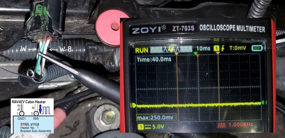
a) the marking of their wires (W-B vs. W) is known (visible in the photo),​
b) check the voltage on each of them - only (2) 1* measurements [*update: connecting the oscilloscope to the white wire (W) and activating the heating for 3-5-10 seconds].​
Q.Is the decision to finally assemble the cabin heater a sign of stopping work to find the cause of its malfunction?

Do I understand correctly that you are convincing us that when the cabin heating is turned on, its cooling is turned on? (Not relevant)
Does the PTC Quick heater turn on? (Not relevant).
 
Last edited:
Just finished coolant delete and did a purge after refilling blue coolant.

check the voltage on each of them
I tested at multiple temperatures as you suggested but heater control signal did not appear on oscilloscope. I ensured needle is making contact by checking continuity on the other side of d15.

20241011_225420.jpg20241011_225402.jpg20241011_225332.jpg20241011_225032.jpg20241011_225028.jpg20241011_223956.jpg20241011_223947.jpg


Pwr is showing up though as it was before.
20241011_232945.jpg20241011_232939.jpg


Is the decision to finally assemble the cabin heater a sign of stopping work to find the cause of its malfunction?
I haven't assembled the heater yet. I am eager to diagnose the cause of heater malfunction.
 
As I understand this test result (attach.), when the heating is turned on, there is no control signal on the RMI contact.

Therefore, only/solely for the final check/testing of the serviceability of the cabin heater itself, I would try to disconnect the contact from the Power Control ECU control and instead connect a simple signal simulator to the RMI input, for example, a Duty Cycle 50% square wave with a frequency of about 40 Hz. For this, you can use a simple NE555 generator https://www.ebay.com/itm/395653609593 or https://www.ebay.com/itm/122369931808 .
Description of NE555 in generator mode in https://howtomechatronics.com/how-i...g-principle-block-diagram-circuit-schematics/.

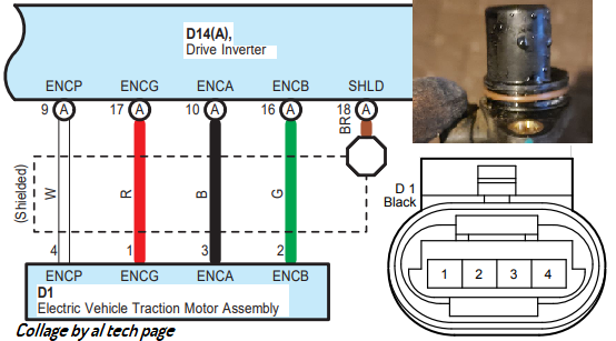
¹/2 off-topic. Can you take a photo of the voltage waveforms on the four contacts of the rotor speed sensor connector when the front wheels are not rotating quickly in READY mode?
A sample/standard of such a check of a working sensor would be very useful for many users of this glorious vehicle, especially with Tesla fault codes for this sensor
DI_f008/DI_w008 hwEncoderA
DI_f020/DI_w020 hwMotorEncoder

p.s. It would not hurt to find out the voltage at this contact if heating is required at the lowest possible temperature.
*
https://alflash.com.ua/2019/to_rav4ev/rmi.jpg
rmi.jpg
 
Last edited:
for example, a Duty Cycle 50% square wave with a frequency of about 40 Hz
Ordering it. It would take 2-3 days to deliver. In the meantime, is there any value in doing a test like it. Putting needles into pwr and RMI at D15 and shorting them for 1s every 5s and checking if the aluminum block heats up? Is it is even safe to do a test like this?

I also have a signal gen function on the oscilloscope but the peak voltage is about 3.5V. That is too low to trigger the electronics, correct?

Can you take a photo of the voltage waveforms on the four contacts of the rotor speed sensor connector when the front wheels are not rotating quickly in READY mode?
A sample/standard of such a check of a working sensor would be very useful for many users of this glorious vehicle, especially with Tesla fault codes for this sensor
DI_f008/DI_w008 hwEncoderA
DI_f020/DI_w020 hwMotorEncoder
Sure. Happy to do it. Do you happen to have a photo handy of which is GND in the speed sensor (Update: Likely I can inspect the wire marking to figure this out). Also, you mean the car must be on jack stands and I run the wheels at a low speed while I take a video of the oscilloscope showing the waveform?


It would not hurt to find out the voltage at this contact if heating is required at the lowest possible temperature.
Not sure I understand. Could you explain how this is different from the test I did above. The photo shows voltage between W and W-B as zero right? W-B is same as any available ground, correct?
 
Last edited:
Ordering it. It would take 2-3 days to deliver. In the meantime, is there any value in doing a test like it. Putting needles into pwr and RMI at D15 and shorting them for 1s every 5s and checking if the aluminum block heats up? Is it is even safe to do a test like this?
I strongly advise against applying power to signal lines.
1. This may damage the device to which this connection will be made.
2. It is possible that the absence of PWM pulses with an amplitude of 12V will be understood by the heater control controller/"driver" as the absence of the need for heating.
Unfortunately, I do not know the description of the algorithm for converting the input PWM signal of the heater control into the output signals of the IGBT Driver IC (1ED020112) control.
I also have a signal gen function on the oscilloscope but the peak voltage is about 3.5V. That is too low to trigger the electronics, correct?


Sure. Happy to do it. Do you happen to have a photo handy of which is GND in the speed sensor (Update: Likely I can inspect the wire marking to figure this out). Also, you mean the car must be on jack stands and I run the wheels at a low speed while I take a video of the oscilloscope showing the waveform?

1. As I understand it, Tesla has many secrets from Toyota and therefore the connection diagram looks like this. Moreover, the speed sensor has been given an idiotic name...
https://alflash.com.ua/2019/to_rav4ev/w_sp_sens.png
w_sp_sens.png

Not sure I understand. Could you explain how this is different from the test I did above. The photo shows voltage between W and W-B as zero right? W-B is same as any available ground, correct?
2. To avoid misunderstandings, I recommend first connecting the ground probe to the case and checking the voltage on all four contacts of speed sensor.
The presence of supply voltage (12V) in the sensor connector can be checked on the disconnected wiring connector.
IMHO. I would understand the abbreviation of Tesla designations as follows:
ENCP mean Encoder Power
ENCG mean Encoder Ground
ENCA mean Encoder (*) Sensor A
ENCB mean Encoder (*) Sensor B
Update
. Yes, you need to check the speed sensor signals during rotor rotation (preferably in both directions).
Or under the influence of inverter voltage or when rotating the wheel manually (taking into account the presence of a differential).
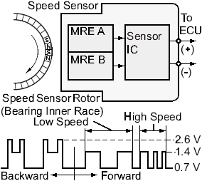
* MRE sensor
https://alflash.com.ua/Sus/speed Sensor3.gif
speed%20Sensor3.gif

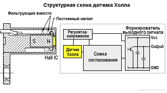
or Hall sensors
https://alflash.com.ua/2019/to_rav4ev/hall_03.gif
hall_03.gif


3. If you are talking about the contacts of the D15 connector, I would like to draw your attention to the fact that
max.U on the W-B (GND1) wire = 0V, vs. on the W (RMI) wire max.U = 250mV.

4. Note. As shown in the video, if the heating temperature is set below the ambient temperature, the heater control voltage stops being pulsed and remains constant at approximately 13V.
It's easy to check... ;)
 
Last edited:
Therefore, only/solely for the final check/testing of the serviceability of the cabin heater itself, I would try to disconnect the contact from the Power Control ECU control and instead connect a simple signal simulator to the RMI input, for example, a Duty Cycle 50% square wave with a frequency of about 40 Hz. For this, you can use a simple NE555 generator
I did this test, it didn't appear to cause the alum heat sink to heat up.

Prep
Configured NE555 timer with appoximately 50% duty cycle and 40Hz.
I couldn't push 3 crocodile clips to D15, so I made a replacement connector where the wires meet the PCB, which maps to GND, RMI and PWR (in this order). Connected all and checked the waveform on the opposite side of replacement connector by inserting a pin. The grooves that go to GND, RMI and PWR were all showing the voltage and waveform we expect.

PWR
20241013_151225.jpg20241013_151234.jpg

RMI
20241013_151303.jpg20241013_151307.jpg


Connected oscilloscope probe to RMI. Turned on READY, heater at 80F and measured temp of aluminum block. Temp was not rising.
20241013_151535.jpg20241013_151654.jpg20241013_151712.jpg

HV DC voltage to cabin heater
20241013_173726.jpg


Test 2

I disconnected the ne555 and connected d15. After a few mins of operation, I was able to see the heater control pwm, but at a very low voltage.
20241013_175037.jpg


Observations:
  1. AC was turning on if it was set to auto which was blowing air colder than ambient even when temp set to 85F. Turning the AC off caused the compressor to turn off
  2. I was able to see the heater control PWM wave only when the seat heater and AC was off. Either of them turning on would create noise on RMI. https://1drv.ms/v/s!AoMSicNQxi7y5kxUESvekQ6Nmm2N
  3. View attachment 20241013_175917.mp4
  4. Seat heater gets automatically turned on when I press
  5. Voltage between RMI (W) and W-B(GND) was the same as voltage with any other ground.
 
To avoid misunderstandings, I recommend first connecting the ground probe to the case and checking the voltage on all four contacts of speed sensor.
The presence of supply voltage (12V) in the sensor connector can be checked on the disconnected wiring connector.
IMHO. I would understand the abbreviation of Tesla designations as follows:
ENCP mean Encoder Power
ENCG mean Encoder Ground
ENCA mean Encoder (*) Sensor A
ENCB mean Encoder (*) Sensor B
I was looking into this but got confused with the colors on the wires. It seems RED (topmost pin) actually is GND? I will double check using the method you suggested tomorrow.
 

Attachments

  • 20241013_194959.jpg
    20241013_194959.jpg
    1.6 MB
I did this test, it didn't appear to cause the alum heat sink to heat up.

Prep
Configured NE555 timer with appoximately 50% duty cycle and 40Hz.
I couldn't push 3 crocodile clips to D15, so I made a replacement connector where the wires meet the PCB, which maps to GND, RMI and PWR (in this order). Connected all and checked the waveform on the opposite side of replacement connector by inserting a pin. The grooves that go to GND, RMI and PWR were all showing the voltage and waveform we expect.

PWR
View attachment 976View attachment 977

RMI
View attachment 978View attachment 979


Connected oscilloscope probe to RMI. Turned on READY, heater at 80F and measured temp of aluminum block. Temp was not rising.
View attachment 980View attachment 981View attachment 982

HV DC voltage to cabin heater
View attachment 983


Test 2

I disconnected the ne555 and connected d15. After a few mins of operation, I was able to see the heater control pwm, but at a very low voltage.
View attachment 984


Observations:
  1. AC was turning on if it was set to auto which was blowing air colder than ambient even when temp set to 85F. Turning the AC off caused the compressor to turn off
  2. I was able to see the heater control PWM wave only when the seat heater and AC was off. Either of them turning on would create noise on RMI. https://1drv.ms/v/s!AoMSicNQxi7y5kxUESvekQ6Nmm2N
  3. View attachment 985
  4. Seat heater gets automatically turned on when I press
  5. Voltage between RMI (W) and W-B(GND) was the same as voltage with any other ground.
In advance, I apologize for my comments and questions.
1. I did not understand everything from your descriptions. For example. We are considering the issue of a malfunctioning cabin heater. But the information about turning on/off the air conditioner and seat heaters is extraneous and causes confusion.
2. There is an excellent tool for checking the operability of the heater - this is checking/monitoring the current from the high-voltage battery on the program screen when changing the duty cycle of the control pulses from the NE555 immiator.
3. Do I understand correctly that when connecting pulses from NE555 generator to the RMI,
a) vehicle was in READY mode?​
b) did the amplitude of the voltage of the control pulses NOT decrease?​
c) did the test last long enough for the large/massive aluminum alloy radiator to noticeably increase its temperature by 5-10 degrees?​
d) does this photo (attachment.1) show an oscillogram of the voltage at the RMI wiring contact (wire W), when this connector is disconnected from the heater or was connected?​
e) does the duty cycle of this signal (attachment) change when the set temperature changes? With this test, you can increase the oscilloscope's sensitivity to voltage (for example, up to 100 mV/div).​
4.
alflash said: ... for example, a Duty Cycle 50% square wave with a frequency of about 40 Hz
Why are the pulses in this photo 4 Hz, not 40 Hz (attach.2)?
 

Attachments

  • 984-deb6a72983b9063088e0b56cf1bd7d0e.jpeg
    984-deb6a72983b9063088e0b56cf1bd7d0e.jpeg
    295.5 KB
  • IMG_20241014_185632.png
    IMG_20241014_185632.png
    1.3 MB
Last edited:
I did not understand everything from your descriptions. For example. We are considering the issue of a malfunctioning cabin heater. But the information about turning on/off the air conditioner and seat heaters is extraneous and causes confusion.
I see. Won't bring this up again.


There is an excellent tool for checking the operability of the heater - this is checking/monitoring the current from the high-voltage battery on the program screen when changing the duty cycle of the control pulses from the NE555 immiator.
I didn't monitor from tpd, but I can repeat the test


did the test last long enough for the large/massive aluminum alloy radiator to noticeably increase its temperature by 5-10 degrees?
I let it run at least 30s. There wasn't any increase in temp

does this photo (attachment.1) show an oscillogram of the voltage at the RMI wiring contact (wire W), when this connector is disconnected from the heater or was connected?
D15 Connected


does the duty cycle of this signal (attachment) change when the set temperature changes? With this test, you can increase the oscilloscope's sensitivity to voltage (for example, up to 100 mV/div).
I didn't notice a difference. I can make a video of it


Why are the pulses in this photo 4 Hz, not 40 Hz (attach.2)?
Goof up. Haven't used an oscilloscope since electrical eng class and I thought the entire screen was 200ms and I configured it to have 8 pulses in that. 😆
Will correct and repeat
 
Do I understand correctly that when connecting pulses from NE555 generator to the RMI,
a) vehicle was in READY mode?b) did the amplitude of the voltage of the control pulses NOT decrease?
Yes. In READY. Scope showed a 1v drop at RMI from 12v to 11v after the replacement connector was a connected
 
Yes. In READY. Scope showed a 1v drop at RMI from 12v to 11v after the replacement connector was a connected
Ok,
I assume that the generator's load capacity is somewhat/slightly small. But I consider the amplitude reduction from 13V to 11 not "criminal" and acceptable.
My "experiences" of checking the heater's heating elements will lead to recommending an increase in the heating time when checking the operability using a control signal simulator.
And monitoring the current from the high-voltage battery (using the program) will improve the adequacy of such a check of the cabin heater's operability.
Successful and productive checks!
 
does the duty cycle of this signal (attachment) change when the set temperature changes? With this test, you can increase the oscilloscope's sensitivity to voltage (for example, up to 100 mV/div).
Here is a video of tests at different temp showing control signal with d15 connected.
https://1drv.ms/v/s!AoMSicNQxi7y5lycb6nnksCMsNwx

Edit: With d15 disconnected, the signal the d15 connector is just noise. I think we already did this test earlier. This is just a double check.
 
Last edited:
Here is a video of tests at different temp showing control signal with d15 connected.
https://1drv.ms/v/s!AoMSicNQxi7y5lycb6nnksCMsNwx

Edit: With d15 disconnected, the signal the d15 connector is just noise. I think we already did this test earlier. This is just a double check.
It's not just interference/electrical noise/interference
At 22 seconds of this video, traces of control pulses with a frequency of about 40 Hz flicker. But then they also disappear.
The reason for their disappearance is a change in the set heating temperature during filming?
In previous videos I did not notice these pulses with this frequency.
.
Does this oscilloscope have a terminal to connect its case to the GND of the car? Are its connection cables shielded?

UPDATE.
It's not just interference/electrical noise/interference


The link is only "for reference"
 
Last edited:
It's not just interference/electrical noise/interference
Agree.In the video I shared, we can see the control signal. What I meant was, without the d15 connected, I only see noise.


At 22 seconds of this video, traces of control pulses with a frequency of about 40 Hz flicker. But then they also disappear.
The reason for their disappearance is a change in the set heating temperature during filming?
Yes, they disappear when temp to lowest (LO)
Does this oscilloscope have a terminal to connect its case to the GND of the car? Are its connection cables shielded?
No grounding, it just just probe connections. Probe ground connected to car a Gnd though.

In previous videos I did not notice these pulses with this frequency.
Correct. If compressor turns on we only see noise. I was able to see this ONLY when compressor and seat heater was off.


Also I am unable to get the ne555 to output 40hz. It jumps from like 10hz to 100hz in the second jumper setting. Is 100hz ok?
 
Back
Top