Charging stopped due to system malfunction

Toyota Rav4 EV Forum

Help Support Toyota Rav4 EV Forum:

This site may earn a commission from merchant affiliate links, including eBay, Amazon, and others.
The fact that the heating elements of this heater are not PTC type is not a limitation for their testing without cooling the radiator with a circulating flow of liquid.
My experiments with them (video in https://www.myrav4ev.com/threads/charging-stopped-due-to-system-malfunction.2692/post-31974) showed that even when the radiator was heated to a temperature of >265°F and only one element, this element remained both electrically and externally completely serviceable.

The severity of the consequences for the pump of it running "dry" is unknown to me. But I assume that they can't remain without consequences as minimum in the long term...

Note. HVAC system have DTC about water temperature sensor
Therefore, this can be an indirect check of the heater temperature.
Although there are multiple cases of cabin heater failure due to a shorted IGBT and, as a consequence, faulty elements of its group.
If replacement is impossible, repair often consists of simply disconnecting the faulty group from the HV power supply.
This reduces the range of temperature adjustment options, but does not deprive the possibility of heating the cabin.
 
Oops. I must have run it dry cumulatively for over 30 mins to do all the tests.


@alflash Given that there was not a big drop in RMI peak voltage when I used the NE555 pwm generator, could we conclude that the heater is not causing the weak heater control signal?
Unfortunately, I don't have the input stage circuit of the RMI signal receiver.
I don't exclude (with a small probability) such a circuit, when the load resistor of this circuit is located on the heating element control board (attach.1).
To check this version/assumption, the photo above shows an illustration of a possible IRM signal check (without connecting to the heater) with a load resistor/load simulator (IMHO 10÷20 kOhm).
 

Attachments

  • 1729497635986_9e8njb_2_0.jpg
    1729497635986_9e8njb_2_0.jpg
    223.6 KB
To check this version/assumption, the photo above shows an illustration of a possible IRM signal check (without connecting to the heater) with a load resistor/load simulator (IMHO 10÷20 kOhm).
I didn't understand this. Are you suggesting I check the resistance between pwr and rmi terminals?

Oh, I think you you mean I use a load resistor on the signal generator output to see the impact on the signal?
 
I didn't understand this. Are you suggesting I check the resistance between pwr and rmi terminals?
No
Oh, I think you you mean I use a load resistor on the signal generator output to see the impact on the signal?
As I assume, the collector of the output transistor of NE555 (pin#3) on the board is connected to both the device output and the load resistor.
I suggest checking (use oscilloscope) the voltage on the D15 wiring connector on pin #3 RMI when a "load" resistor from the +12V pin #2 is connected to it and when disconnecting this connector from the cabin heater.
This will simulate such a construction of the input circuit of the cabin heater.
https://alflash.com.ua/2019/to_rav4ev/connecting1.jpg shows an example of connecting oscilloscope probes during a similar test.
 

Attachments

  • IMG_20241021_105100.png
    IMG_20241021_105100.png
    6.1 KB
Last edited:
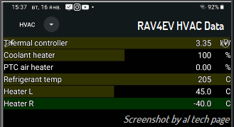
I wonder if the cabin heater parameters are among these data...
 

Attachments

  • IMG_20241022_191251.png
    IMG_20241022_191251.png
    427.1 KB
  • IMG_20241022_192653.png
    IMG_20241022_192653.png
    1 MB
As I assume, the collector of the output transistor of NE555 (pin#3) on the board is connected to both the device output and the load resistor.
I suggest checking (use oscilloscope) the voltage on the D15 wiring connector on pin #3 RMI when a "load" resistor from the +12V pin #2 is connected to it and when disconnecting this connector from the cabin heater.
This will simulate such a construction of the input circuit of the cabin heater.
I have ordered some potentiometers to test this. Could you confirm if these are the two tests you want me to perform?

I will disconnect d15 connector. On this replacement connector I have made to create artificial heater control using ne555 , I will connect a 10kohm resistor between PWR and RMI. I will take 2 measurements

1. Without connecting it to the heater pcb
2. After connecting the replacement connector to the heater pcb
 
Use an oscilloscope to check the RMI signal (of D15) without connecting it to the heater, but with a 10kOhm fixed resistor connected between its pin (#3) and the PWR pin (#2). Compare the signal with and without this resistor and maybe that (step 1) will be enough.
Your replacement connector photo?

p.s. If you have five minutes to spare, please check the fault codes in HVAC system (w/o scan tool) with the pump connector removed and the cabin heating turned on.
 
Last edited:
Back
Top