Charging stopped due to system malfunction

Toyota Rav4 EV Forum

Help Support Toyota Rav4 EV Forum:

This site may earn a commission from merchant affiliate links, including eBay, Amazon, and others.
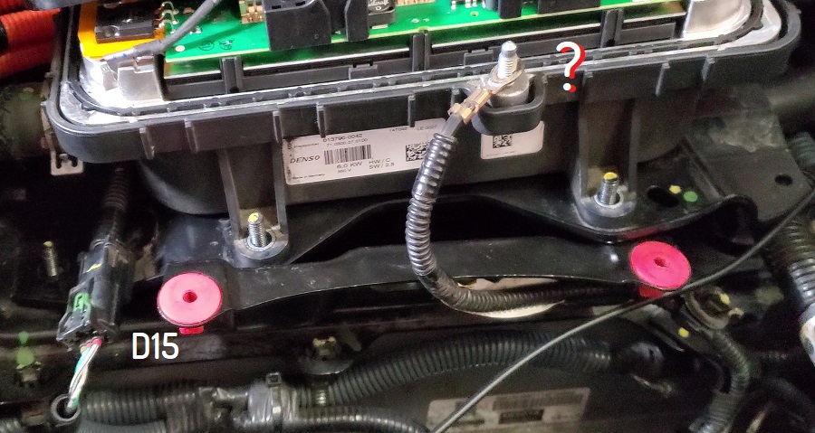
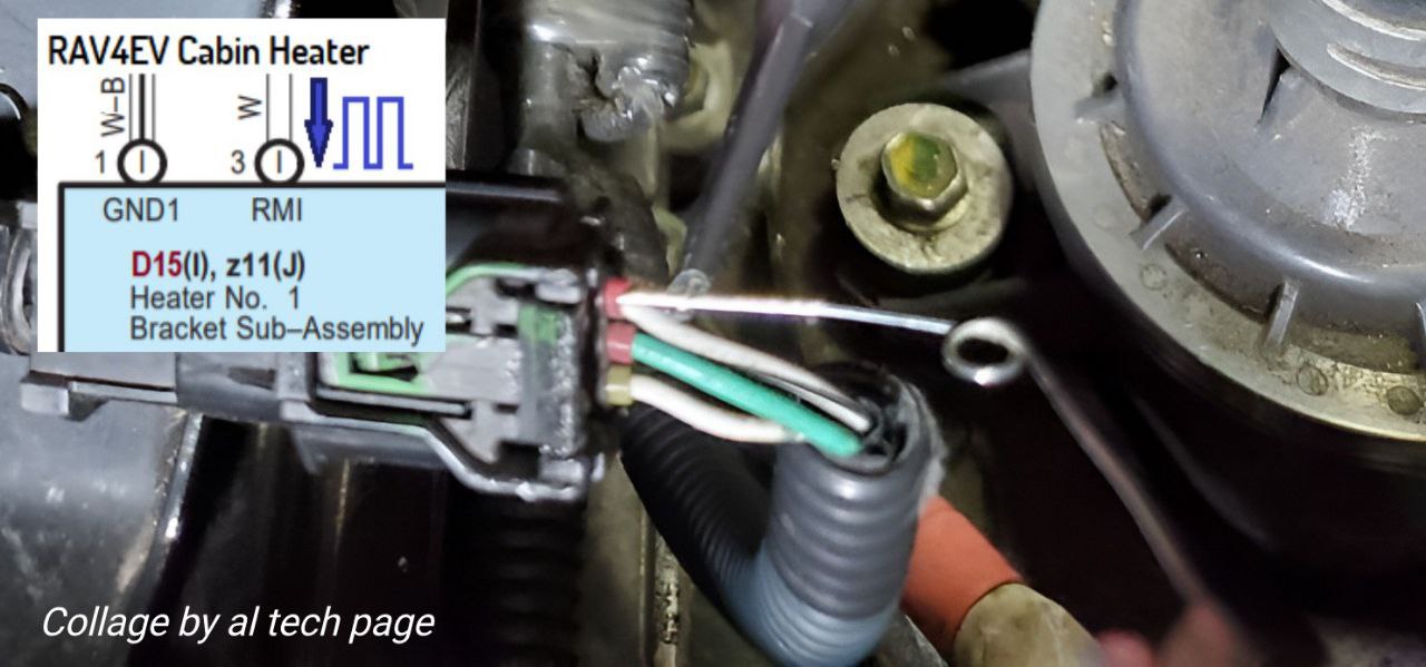
Aargh, sorry about the confusion and frustration caused to you. I thought the bottom right of https://alflash.com.ua/2019/to_rav4ev/cab_heat_w.png is D15. I will repeat the test properly soon. The screenshot above helped.


In the screen recording of TPD, the temp was at "HI". Ambient temp was at 64 degrees F, but the compressor was running every 10 seconds or so.
I apologize for the ambiguity.
I corrected it as best I could
Update.
https://alflash.com.ua/2019/to_rav4ev/cab_heat_w2.png
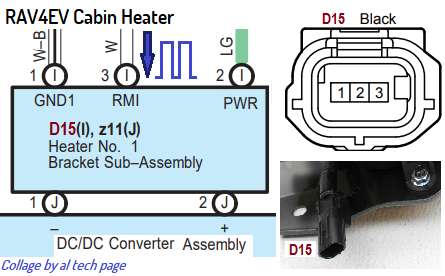
cab_heat_w2.png


I don't know if RAV4EV has AC drying mode.
 
Last edited:
The seat heater was not active during this test. When there is increased current draw I have noticed that the marked part in the pic below is vibrating and there is some noise coming from it. Is it the compressor?
View attachment 925
The indicated part is either a muffler or possibly a receiver/dryer, both part of the A/C system. The A/C compressor is just below and to the left, in your picture.

The A/C compressor is run by HV, so it won't run if the contactors aren't closed.

The Cabin Heater (water heater) is run by HV.

The seat heaters are 12v.

The PTC "Quick Heater" is 12v. More info on it is in this post.

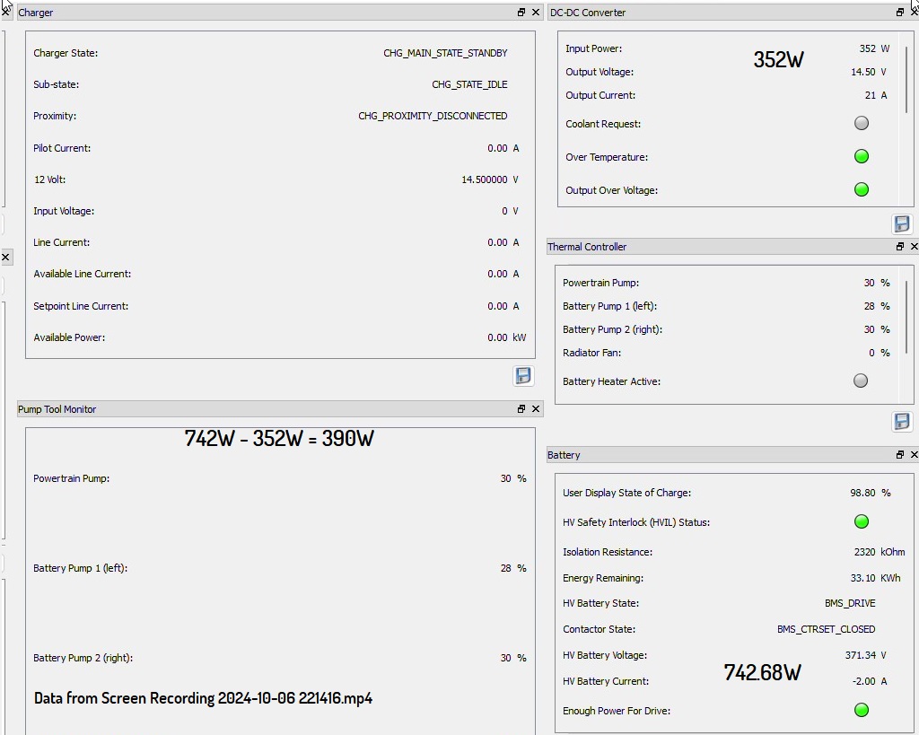
12v accessory loads will cause the DC-DC Converter to draw more HV, so that will be reflected in TPD, but the end point is still 12v.
 
  1. Zeroing clamp meter - 20241005_205858.mp4
  2. Continuity check of oscilloscope probes to the cabin heater plug terminals. I found that it was easier to connect oscilloscope probes to heater pcb. - 20241005_205648.mp4
...
I did a screen recording but it didn't save properly. I will redo the test tomorrow and update here. It was 370V with 3-5A draw when the heater was on and 0.7A when it was off.
1. Was there current flowing through that wire when the zero button was pressed?
2. Photo of readings of the current clamps stationary after zero calibration after turning on the interior heating?

Video "Screen Recording 2024-10-06 221416" is no sign of current flowing through the heating elements of the cabin heater. ...
https://alflash.com.ua/2019/to_rav4ev/frame at 0m20s.jpg
frame%20at%200m20s.jpg


The heater was tested with the heating set to 90°F?

p.s.
Why isn't this terminal screwed in???
https://alflash.com.ua/2019/to_rav4ev/20241006_115628_.jpg
20241006_115628_.jpg
 
Last edited:
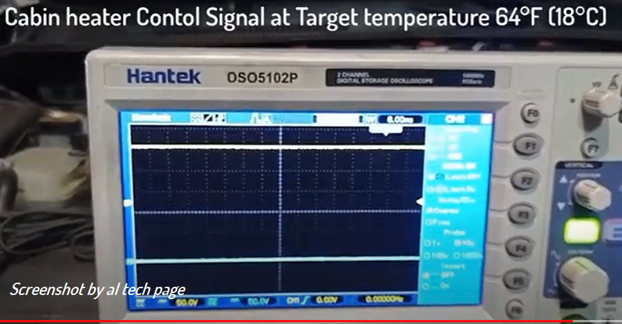
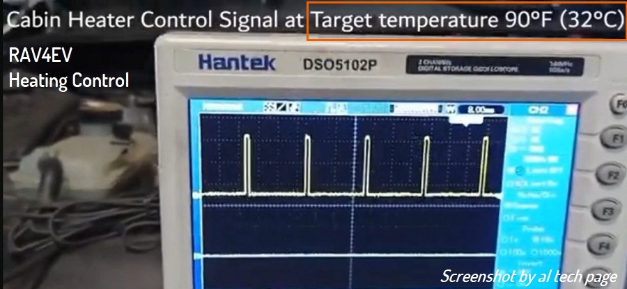
oscilloscope to the connector (D15*) and check (compare with the example) the cabin heater control signal.
I put a small wire into the rmi terminal on d15 and connected positive probe to it. Connected ground to one of if the ground connections available. I see no signal. I hope I have connected it properly this time.
 

Attachments

  • 20241007_093752.jpg
    20241007_093752.jpg
    1.9 MB
  • 20241007_093934.jpg
    20241007_093934.jpg
    5.6 MB
I put a small wire into the rmi terminal on d15 and connected positive probe to it. Connected ground to one of if the ground connections available. I see no signal. I hope I have connected it properly this time.
1. To double check, I would connect an oscilloscope and take a photo of data from remaining two contacts.
For example, to check whether the heater has 12V power

2. An example of a control signal when the temperature in the cabin is higher than the set temperature and the heater does not work.
https://alflash.com.ua/2019/to_rav4ev/no_heat.png
no_heat.png

Note. This is a fragment of a previously recommended video ...
Why not use a pin to connect? :)

3. It is possible that the output stage of the signal source is implemented according to the "open collector" scheme, and the load resistance is located in the receiver (in this case, in the heater). Therefore, I would like to check the voltage oscillogram on this contact, with the D15 connector connected.
 

Attachments

  • pin.jpg
    pin.jpg
    60.7 KB
Last edited:
Was there current flowing through that wire when the zero button was pressed?

Before zero adjustment: 0.03A
Screenshot_20241007-133534_Gallery.jpg

After zero adjustment: 0.001A
Screenshot_20241007-133733_Gallery.jpg


Photo of readings of the current clamps stationary after zero calibration after turning on the interior heating?
Reading 0.001A
Screenshot_20241007-155859_Gallery.jpg


heater was tested with the heating set to 90°F?
Temp setting doesn't go that high. It just says "HI" at the maximum setting.


p.s.
Why isn't this terminal screwed in???
I was being lazy after putting back the heater assembly. I did ensure that they were making contact by a continuity check. I will bolt it down now.


For example, to check whether the heater has 12V power

If I understand correctly, you are suspecting that if load is disconnected we may not see the right signal. I found it easier to tap into where the D15 wire meet the PCB (the original bottom right picture. I connected the hook probe to each of the (non-ground) pins.

Yes. I see 13.5v at pwr pin at the connector on the PCB (right most pin)
20241007_154206.jpg

Middle pin (Control signal?)
0V
20241007_154420.jpg


IMPORTANT UPDATE
I noticed the air blown was colder than ambient temp and when I checked with thermometer I actually found that the temperature was decreasing. Is AC turning on while it should be heating?!?!
https://1drv.ms/v/s!AoMSicNQxi7y5ikVfI6cgNjAaU7h?e=hQP1kg
 
...
Temp setting doesn't go that high. It just says "HI" at the maximum setting.
...
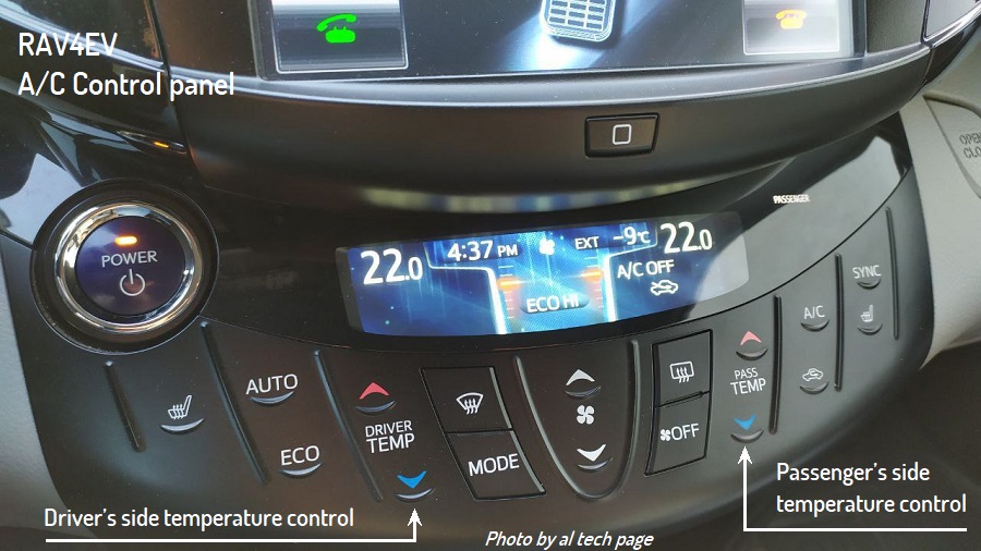
Dear Sir, please
1. Watch the video I recommended earlier...
This is a screenshot of a fragment of it
https://alflash.com.ua/2019/to_rav4ev/ac_control.jpg
ac_control.jpg


2. Pay attention to these temperature control buttons...
https://alflash.com.ua/2019/to_rav4ev/acfin.jpg *
acfin.jpg


3. Maybe you will find time to look at this video ...

--------------------------------------- This was written before the IMPORTANT UPDATE


Update.
4. Set the heater to 90°F and check the heater control oscilloscope signal with the D15 connector connected (using the pin on the back/rear side of the connector to connect, as show in https://alflash.com.ua/2019/to_rav4ev/connect.jpg).

5. Just in case, check the A/C fault codes (w/o scan tools)
 
Last edited:
Set the heater to 90°F

In my car, the temp setting goes from 85 to "HI", there is no 90 degrees setting

check the heater control oscilloscope signal with the D15 connector connected (using the pin on the back/rear side of the connector to connect


Temp Setting: HI and AC off, mode set to NORMAL
20241008_093210.jpg


Air colder (61F) than ambient temp (64F) blowing even when AC is off and heat is on.
20241008_093307.jpg

PWR: 13.8V
20241008_093740.jpg20241008_093336.jpg

RMI - No signal. (I double checked the needle is making contact by disconnecting D15 and checking continuity between the inserted needle and the other side of the connector)
20241008_095603.jpg20241008_095704.jpg


Just in case, check the A/C fault codes (w/o scan tools)
I think you mean using regular OBD scanner? Will check.
 
Quick answer.

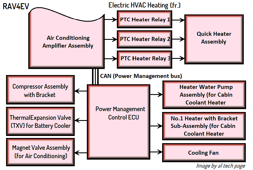
At this time, if the heater is receiving high voltage, but there is no control signal from the Power Management Control ECU*, then I can only suggest one thing.
Check the A/C–B fuse (7.5A) in the Motor Compartment Relay Block No. 2 (under the hood in the right box).

I would set the oscilloscope sweep to 5 or 10 milliseconds per division (200 microseconds is too short).
I would press the "down" button once to see the degrees F :)

* https://alflash.com.ua/2019/to_rav4ev/heat_control.png
heat_control.png
 
Questions (²/5 off-topic).
1. In phoro (attach.1).
2. During this check, is the heating system fully assembled and the "Air Purge" procedure performed?
3-4. In attach.2.
5. I wonder if the heating elements of the Quick-heater turn on when the maximum cabin heating is set and under other required conditions...
6.
 

Attachments

  • IMG_20241009_120916.png
    IMG_20241009_120916.png
    390.7 KB
  • IMG_20241009_123032.png
    IMG_20241009_123032.png
    200.2 KB
Last edited:
... RMI - No signal. (I double checked the needle is making contact by disconnecting D15 and checking continuity between the inserted needle and the other side of the connector)
View attachment 936View attachment 935
Dear Rakesh Suresh, Please excuse my inattention.
Cito.
Please confirm that this picture of yours shows voltage check on W-B white wire with black stripe (pin GND 1), but not on W white wire (pin RMI)?
https://alflash.com.ua/2019/to_rav4ev/d15conn.jpg
d15conn.jpg


If so, please repeat the RMI signal checking at different (2-3) set temperatures.
 
Last edited:
It was blowing cold air, so I reduced fan to minimum.


During this check, is the heating system fully assembled and the "Air Purge" procedure performed?
No, the coolant hoses aren't even connected to the heater. I was hoping the air is at least ambient temp if not warmer and wanted to see the aluminum in heater assembly heat up, but neither happened. Instead it was blowing air colder than ambient temp

In attach.2
User display state of charge is 98.8% in TPD. I will check the life time energy discharged next time I test. (The GoM showed low value after turning the heater on. If I turn off heat, the GoM jumps to 115).

Please confirm that this picture of yours shows voltage check on W-B white wire with black stripe (pin GND 1), but not on W white wire (pin RMI)?
Yes, the pin is on the wire with a black stripe. I double checked pin 3 (RMI) in this https://alflash.com.ua/2019/to_rav4ev/cab_heat_w2.png Does the top right have GND and RMI flipped, or am I reading it wrong? So, I will to place the pin on the white wire and test at 3 diff temp settings.

I am in the middle of a coolant delete and I have drained the blue coolant. I presume it is not safe to get car to READY without the coolant. I will resume working on the stuff you suggested after I refill it. Please let me know if you think it is OK to test heater with blue coolant drained.
 
With blue coolant drained, the battery heater (Zero-Start brand) could be damaged, if the BMS commands battery heat. I doubt the pumps would be harmed by a bit of running dry -- which is usually a no-no for fluid pumps -- but that battery heater . . . I don't think I would take a chance on it being fired up without liquid.

Also, the cabin heater isn't PTC, so testing without pink coolant is kind of a gamble too, for the same reason: it is not PTC (intrinsically safe), therefore an external mechanism has to shut it down if it overheats, and without working fluid, that external mechanism might be too late.

That said, I forgot to refill the pink reservoir when I did my OBC fuse replacement, and the cabin heater didn't like that at all; it didn't fry, but I don't know why it didn't, since it definitely ran abnormal for a minute and steamed a bunch when it finally got the pink stuff it wanted. Not recommended.
 
On the "blowing colder than ambient" thing . . . the numbers I saw were only around 5°F different (duct discharge temp vs ambient) and that's within the range of measurement error, esp. if taking measurements on a car that's been outside overnight, and testing in say late morning, when the ambient has risen but the car's parts are still being dragged up to an ever-rising ambient. The heater core is buried in insulating materials and could remain much cooler than outdoor air, so I wouldn't be all that surprised by a 5 or even 10° delta, at least for a minute or so.

Now, if the A/C compressor runs at all, then yeah, cold air is going to be there, but probably closer to in the 40s than only 5° low.

If you were testing in early evening, then forget all the above.


Write your reply...
Back
Top