Thanks both for your comments.
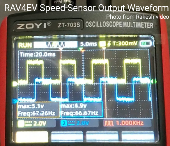
@asavage, your car seems to have a good ENCG connection. Try measuring the voltage between ENCP and ENCG with and without the sensor (ready mode, neutral). It should be almost the same. Then with the sensor connected (ready mode, neutral), measure the voltage between ENCA and ENCG. The high value should be exactly the same voltage as ENCP and ENCG and the low value should be almost 0V. Rotate the wheels or driveshaft or something similar and it should switch between both values. Then do the same between ENCB and ENCG. Just to confirm, also measure the resistance between ENCG and chassis ground. I think it should be almost 0 ohm.
From what I've seen, these are the correct values (from alflash's previous post and from my test):
ENCP and ENCG are almost 5V (mine is almost 4V when failing)
ENCG and chassis ground 0V (mine is around 1.3V when failing)
ENCA, ENCB to ENCG should be almost exactly like ENCP when high and almost 0V when low.
On my car, I suspect that the diode mentioned in my post is causing an abnormal voltage between ENCG and chassis ground. I've measured all the grounds on D14 between GND 11 and the throttle grounds (ACGD 15, ACG2 22) and it shows 0 ohms. I assume ENCG should also be 0 ohms, but it shows more than 20 ohms (that's why on my car ENCG and CG show 1.4V when the encoder is connected and the car is in D). I tried shorting ENCG to CG but the car failed when releasing the brake pedal in D.
So my next step will be to feed external 12V into D14 via(pin 1 IGDI and 11GND) to the main board outside the drive inverter and try to find the diode or whatever faulty component is causing the high resistance value of ENCG. I hope the board doesn't block itself as it won't detect anything else connected to it.
If I can't find the faulty component on the board, I'll try powering the encoder with the throttle power supply as it's also a 5V output and disconnect it from the encoder power supply (ENCP and ENCG).


 https://alflash.com.ua/2019/to_rav4ev/enc_data.pn


