My turn for the Check EV message

Toyota Rav4 EV Forum

Help Support Toyota Rav4 EV Forum:

This site may earn a commission from merchant affiliate links, including eBay, Amazon, and others.
Ready mode voltage between ENCG and Chassis ground is 1.3V
!!!
between CG and SG pins of DLC3 is 0V
Thanks for info.

Exceptional IMHO. In my vehicle I would connect the ENCG contact to the chassis ground via a 12V 1÷5W lamp.
And I would check the system's behavior with such an additional connection.
As I understand it, there is a missing or poor contact with the ground somewhere.
 
All these diodes all measure open in both directions but the one with the letter b measures 20 ohm in both directions. also all of them are connected to Chassis Ground(GND). I think all of them are the same and possibly serve as some kind of protection. Since the one with the letter b is connected to ENCG and is almost shorted to chassis ground, that could be the error.

Is there possible that someone with a working car, test the resistence between ENCG on D1 and chassis ground???? while the vehicle is off.


WhatsApp Image 2024-11-20 at 12.53.47 PM.jpeg
 
nevermind, there are two 40 ohm resistors in paralell between CG and ENCG.

If someone can check the resistance between this two point will be highly appriciated.
 
On my broken RAV4:

In Ready/Park, measuring ENCG to chassis ground (below: black clip lead on drive unit mounting bolt on frame).
IMG_9535.jpeg

IMG_9536.jpeg

IMG_9538.jpeg

In Drive (brake applied) (during this test, the drive unit was in working condition, could drive the wheels/could have been driven. But it would error and stop if driven much)


IMG_9539.jpeg

This is not on a "working" vehicle; it has the same issues as yours does: sometimes it will drive, sometimes it will not.
 
Last edited:
nevermind, there are two 40 ohm resistors in paralell between CG and ENCG...
+
Ready mode voltage between ENCG and Chassis ground is 1.3V ...
->
If a voltage of 1.35V drops across a 20 Ohm resistance, then according to Ohm's law, a current of I = 1.35 : 20 ~ 0.067(A) flows through it.
Isn't this too much current for this speed and direction sensor? (IMHO. Maybe two MRE Sensors*).

In addition, we already know the output voltage of "zero" and "one" of both (A and B) encoders on a good vevicle: https://alflash.com.ua/2019/to_rav4ev/enc_data.png

* It would be useful to check the encoders signals when moving the screwdriver tip near the side surface of the sensor when it is removed from its "socket" but remains connected to the D1 connector in Ready mode ...
 
Last edited:
Thanks both for your comments.

@asavage, your car seems to have a good ENCG connection. Try measuring the voltage between ENCP and ENCG with and without the sensor (ready mode, neutral). It should be almost the same. Then with the sensor connected (ready mode, neutral), measure the voltage between ENCA and ENCG. The high value should be exactly the same voltage as ENCP and ENCG and the low value should be almost 0V. Rotate the wheels or driveshaft or something similar and it should switch between both values. Then do the same between ENCB and ENCG. Just to confirm, also measure the resistance between ENCG and chassis ground. I think it should be almost 0 ohm.

From what I've seen, these are the correct values (from alflash's previous post and from my test):
ENCP and ENCG are almost 5V (mine is almost 4V when failing)
ENCG and chassis ground 0V (mine is around 1.3V when failing)
ENCA, ENCB to ENCG should be almost exactly like ENCP when high and almost 0V when low.

On my car, I suspect that the diode mentioned in my post is causing an abnormal voltage between ENCG and chassis ground. I've measured all the grounds on D14 between GND 11 and the throttle grounds (ACGD 15, ACG2 22) and it shows 0 ohms. I assume ENCG should also be 0 ohms, but it shows more than 20 ohms (that's why on my car ENCG and CG show 1.4V when the encoder is connected and the car is in D). I tried shorting ENCG to CG but the car failed when releasing the brake pedal in D.

So my next step will be to feed external 12V into D14 via(pin 1 IGDI and 11GND) to the main board outside the drive inverter and try to find the diode or whatever faulty component is causing the high resistance value of ENCG. I hope the board doesn't block itself as it won't detect anything else connected to it.

If I can't find the faulty component on the board, I'll try powering the encoder with the throttle power supply as it's also a 5V output and disconnect it from the encoder power supply (ENCP and ENCG).
 
Last edited:
Q.
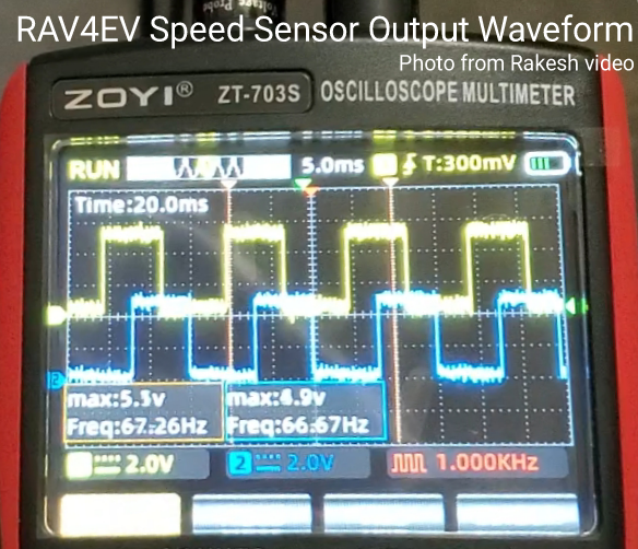
1. Are there any results* of checking the sensor voltages when
a) using different sensors;​
b) using an oscilloscope?​
2. What is the voltage between ENCG and Chassis GND in those short minutes when the car is running normally,
3. If possible, check the current when connecting ENCG and Chassis GND via an ammeter.
* It would be useful to check the encoders signals when moving the screwdriver tip near the side surface of the sensor when it is removed from its "socket" but remains connected to the D1 connector in Ready mode ...
4. Can you perform this check "on the table" / without RAV4EV, using this method by supplying power to the sensor from an external source?
 
Last edited:
Q.
1. Are there any results* of checking the sensor voltages when
a) using different sensors;​
b) using an oscilloscope?​
2. What is the voltage between ENCG and Chassis GND in those short minutes when the car is running normally,
3. If possible, check the current when connecting ENCG and Chassis GND via an ammeter.

4. Can you perform this check "on the table" / without RAV4EV, using this method by supplying power to the sensor from an external source?
Hi,

1. a) yes cheked with the original revision B and a cheap one revision C and are the same results.
b)I don't have oscillospe, readings only from multimeter.
2. Cannot confirm since car was working less each time and right now is disassembled.
3. 58mA
4. With an external power supply without the main board the voltage didn't drop when connecting the sensor.
 
Back
Top