OK to drive with BMS_f038 code?

Toyota Rav4 EV Forum

Help Support Toyota Rav4 EV Forum:

This site may earn a commission from merchant affiliate links, including eBay, Amazon, and others.

Jsnx

***
Joined
Mar 25, 2023
Messages
5
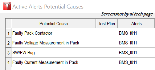
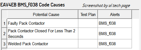
My 2013 RAV4EV recently died on the freeway. I hit the accelerator to change lanes, the was a clun,k and I lost all power. I got safely to the side of the road, tried waiting and restarting a few times, then called for a tow. Wife and I traded cars, and she waited for the truck. When the to came, she was able to get the car moving enough to help get it loaded. Maybe between us we did the 'on/off 5 times magic spell'. Anyway, car was towed to Magnussen's in Palo Alto. Their diagnosis is that we need a new battery pack. Many codes in their diag report (Toyota P312F-448, BMS_f001, DI_f037, BMS_f011, BMS_f038), but the last (BMS_f038) seems most relevant.

Car is driveable now, but the Check EV System warning is still there. If I have a contactor problem, is it likely to cause me to lose power again under normal driving conditions, or only if if I hit the 'gas' for hard acceleration? I can reign in me need for acceleration if that will reliably get me 30 miles for my daily commute.

This forum was very helpful a few years back, when I replaced the OBC fuses to breathe more life into my car.

Looking for another breath of fresh electrical driving,
Jeff
 
You're on borrowed time; contactors will not get better, only worse. After getting that error code, I got about 5 short trips out of my RAV4 before the contactors completely failed and left me stranded.

Replacing the contactors isn't that hard, about on par with replacing OBC fuses. However you'll need to have access to a vehicle lift, maybe via a local independent mechanic.
 
Last edited:
Totally agree if you can find a local mech with a lift and get the pack dropped to get it open and look at the contactors. The old OEM white ones will probably be toasty or burnt/ brown if they are getting bad like mine was... they seem to be failing fast now.
 

Attachments

  • Rav-toasted contactors1...jpg
    Rav-toasted contactors1...jpg
    102.4 KB · Views: 0
For Clarification.
Quote from RAV4EV RM (Doc ID: RM000005CIQ00FX)
DTC BMS_f038 Contactor Fault.
DETECTION CONDITION: There is a short in the high-voltage negative circuit while the contactor is ON.

https://alflash.com.ua/2019/to_rav4ev/f011.png
f011.png


HTH,
 
Last edited:
Thanks all for the info. I have not yet searched online. Is there a recommended source for new contactors?

I'm not committed to the repair just yet, my time being the limiting factor. I know the risk in continuing to drive. We'll see how much time I can borrow. I like the idea of doing the repair, there's a certain satisfaction in being able to fix unusual things.

Meanwhile, I'll update here with my experience, good and bad. Driving will be in town errands, or my 30 mile round trip commute (successfully executed twice so far). From an electro-mechanical perspective, it seems to me that hard acceleration induced the initial failure, due to a power surge through the contactors. I'm avoiding that, but not used to being out of the fast lane. The sacrifices we make for our cars.

Jeff
 
https://octopart.com/2098372-1-te+connectivity-46447745
https://pl.farnell.com/en-PL/te-con...m/contactor-relay-spst-no-dm-12vdc/dp/2885513
https://www.te.com/en/product-2098372-1.html

The suspiciously low price here raises the assumption of a fake https://www.ebay.com/sch/i.html?_fr...&_sacat=0&_odkw=contactor+12+evc500&_osacat=0

p.s.
For Clarification.
Quote from RAV4EV RM (Doc ID: RM000005CIQ00FX)
"...DTC BMS_f038 Contactor Fault.
DETECTION CONDITION: There is a short in the high-voltage negative circuit while the contactor is ON
..."
https://alflash.com.ua/2019/to_rav4ev/f038c.png
f038c.png
 
Last edited:
Add me to the BMS_f038 club. I'm sitting in the parking lot of a Harbor Freight (don't ask), awaiting the arrival of my "AAA prepaid tow". Just rolled up to 123k miles, but the pack was replaced under warranty about five years ago for the same problem.

Untitled_20240827_1.png

---

Interestingly, with the brake pedal depressed, pushing the Power button will not turn off the system. Only releasing the brake pedal then pushing the Power button will turn it off.
 
Last edited:
My heirs will be amused at the tools I've amassed -- good guess -- but no. In the semi-rural area I've moved to, if what you want isn't at HD or Ace, it has to be shipped -- and I've cut way back on Amazon as a logistics/fulfillment vendor because 1) awful products are their mainline; 2) you can't know that what you've received is genuine, since much of what Amazon brokers isn't fulfilled by Amazon but by 3rd parties, plus you sometimes receive stuff other people have rejected & returned; 3) counterfeit stuff; 4) dangerous stuff; 5) Bezos' latest Prime money-grab ("pay more for commercial-free Prime") pushed me to drop Prime, making Amazon even less attractive than buying directly from vendors or distributors.

I needed some 4.5" x 1/8" x 7/8" hub grinder disks, and the Diablo stuff I wanted isn't available from HD anymore; I stopped in, after a 100 mi. drive, to pick up $20 of HF's Warrior/Bauer/other-cheap-brand disks to get through a job on my dump truck the next day. I don't habitually buy tools at HF -- esp. power tools, since a former boss insisted on Chicago Electric stuff, I had a big box of failed units in our shop -- but there are things they sell that are both reasonably priced and reasonable quality. Their small 1000 lb dollies for $15 after tax are a bargain for rolling, say, transmissions under a workbench, etc. Don't put 1000 lbs on one; we did, once. Doesn't roll. But they're great for lighter stuff.
 
Last edited:
Pack has been removed. For reference, from the Service Manual:
HV Battery Components
HV Battery Removal
HV Battery Installation

I may not have needed to, but I added 2x8" extensions my lift table, from 44" to 60". It might have been OK without, but I felt better with it supported more fully. The lift table capacity is 1000kg/2200 lbs. The HV Battery is reported to weigh ~862 lbs.

IMG_8937.jpg IMG_8939.jpg

Removing the LF wheel makes clearing the battery much easier, IMO. I removed both left wheels just to make it a bit easier for me.

IMG_8941.jpg IMG_8942.jpg IMG_8943.jpg

IMG_8944.jpg IMG_8945.jpg IMG_8946.jpg

For a battery that was warranty replaced in 2019, it's pretty dirty, with some embedded mud in the Torx fasteners.

IMG_8953.jpg IMG_8951.jpg

[10 pic limit reached]
 
IMG_8955.jpg IMG_8956.jpg

I reinstalled the Service Disconnect -- which contains a seal near the top -- and gave the whole top a bath, Dawn & a terry washcloth.

IMG_8957.jpg IMG_8963.jpg IMG_8971.jpgIMG_8960.jpg

There are some areas where the lid paint has bubbled from corrosion.

IMG_8962.jpg

I'll be disassembling this (later: have disassembled) to see if a fix can be accomplished for the dehumidifier air pump that has gone silent.

IMG_8972.jpg IMG_8973.jpg IMG_8976.jpg
 
Last edited:
The four HV cable glands:
  • Large ones on passenger side = LDU
  • Small ones on driver's side = HVJB @ passenger side of the OBC. The manual calls them "charge cables", which is misleading
I'm not wearing my HV gloves in this pic, because I've already checked the terminals with a voltmeter (see Service Manual procedures, linked previously).

After unbolting the four cables -- leave the fuse alone -- the cables are supposed to just pull out, but you don't want to damage them -- they're very expensive -- and from previous experience, yanking on them can compromise the cable/gland interface and lead to a frustrating reassembly side-trip. Be gentle. Use pliers where you can, to twist the glands in the housing whilst pulling.
IMG_8925.jpg

The control cable is latched in a not-very-intuitive way. The latch is on the bottom. Service Manual hints to "lift the claw". Yeah. Looking toward the rear of the car:

IMG_8929.jpg IMG_8933.jpg IMG_8935.jpg

I admit that I lowered the battery ~6" and then was able to see the connector at the same time as reaching in with a o-ring pick tool to "lift the claw". It popped right off, then. This is where it mates:

IMG_8947.jpg IMG_8948.jpg

[later]
I obtained some better pictures of the "claw". You can't press on anything to release this, you have to pull down toward the ground ("lift") this catch, and you can't both see it and use a tool to "lift" it at the same time, until the battery is lowered a bit. You can do it by touch, I assume.

IMG_9042.jpgIMG_9043.jpgIMG_9044.jpg

Interesting that much of this connector is not populated:
IMG_9047.jpg
 
Last edited:
Asavage,

Can you describe "lifting the claw" to remove the control cable a bit more? I see a bit of blue showing on the bottom of the socket prior to your removal. Is that the target of your o-ring pick?

I'm still rolling the dice and driving the car 850 miles after my initial posting. I know my luck will eventually run out, and your contributions here will be very helpful.

Good luck with the rest of the project!
Jeff
 
Jeff, I crawled under the car and took a few more pics, and added them above.

---

To remove the lid, the dehumidifier harness has to be disconnected. It looks as if you can leave the dehumidifier in place and disconnect it from underneath the lid once it's raised, though that's not what I did, since my dehumidifier had to come apart ASAP due to the failed motor.

Next, the Service Disconnect + fuse surround has to be removed. This is only the outer square ring as shown; there is no need to remove the inner four screws. Note that dirt (and water, in my case) collects below flush around this surround. I used compressed air to blow it out thoroughly before removing the four screws.

Like most of the other pack screws that are Torx, these are T25.

IMG_9009.jpg IMG_9010.jpg

And, the BMS cover must be removed, because the Controls connector harness, a jumper harness to a daughterboard, and a ground strap have to be disconnected. As Jame Klafehn notes in his YT series, the screws retaining this cover require either a 5.5mm or 3/32" socket -- which is only .003"/.1mm larger; six-point is preferred here. Once that cover is lifted, disconnected, and removed, the lid can be removed.

IMG_9011.jpg IMG_9013-1.jpg IMG_9015.jpg

A whole bunch of lid screws later, I used a putty knife to break the seal on the entire front edge, then used plastic door shims to hold up freed sections, until the whole front edge was lifted about 1/4" With the pack out in the sunshine and the lid quite hot, I could then use my hands to apply more upforce to the front lid edge, and about 15 seconds of steady pressure broke the sides free.

IMG_9016.jpg IMG_9017.jpg IMG_9018.jpg

I put two of the rear "tower" mount bolts back in their holes; the "tower" mounts are removed before dropping the pack, if you follow Toyota's directions. Putting two bolts back in kept the lid from wanting slide off -- much later in the process.
 
The sealing goo is either butyl tape or something quite like it. It's not silicone/RTV. It has the appealing property of being more attracted to itself than to the painted surfaces it's glued to (but it prefers fibrous/high surface area stuff like linen, paper towels, and finger skin even more). I took advantage of this property and used it to remove the goo. I scraped up enough to form a small ball, then repeatedly pushed the ball onto a goo surface, then pulled it back off. Like taffy pulling, except unlike taffy, this stuff will mostly stay with your hand-held ball of goo, and come off the painted surfaces. Slowly.

I used a plastic spudger to scrape the mass off, to minimize the amount of goo I was trying to remove via the above method, and that sped things up. I would say that 99% of it comes off using this method.

I knew that typical nitrile/latex gloves would not be up to this, so I first tried this bare-handed, which worked fine, as long as you don't need that hand to do anything else, ever. After my attempt to do that and then needing a break, I used coconut oil and worked it into my skin to break free the goo's adhesion to my hand skin. It all eventually came off this way, except under fingernails, which I'll leave alone.

After that, I dedicated a leather glove to the project, and as the goo ball got larger, it made handling it easier.

IMG_9034.jpg IMG_9035.jpg IMG_9036.jpg IMG_9037.jpg IMG_9038.jpg IMG_9039.jpg

I'm about 80% complete, with the lid propped in place as shown. Tomorrow, I'll remove the lid onto a safe surface, then finish goo removal. The battery has been moved indoors to avoid condensation which was evident even under a tarp after one night outdoors (prior to lid removal, so none inside). I would have used a tarp and small heater underneath the pack, had I had to leave this outside/tarped another night. The large thermal mass means that every morning the surrounding air warms faster than the cold pack, and avoiding condensation is really hard in that circumstance.
 
In preparation for replacing the contactors . . .

IMG_9019.jpg

I wanted to remove this BMS mounting plate ground strap:

IMG_9041.jpg IMG_9021-1.jpg

However, the screw affixing it to the BMS mounting plate to the top of the battery module below it . . . well, it screws into a metal nutsert that's molded into . . . plastic. Either the screw is cross-threaded, or Tesla used an anaerobic sealant with adhesion properties higher than the nutsert's OD to the plastic it's embedded in. The screw backed out 1/2 turn, then the nutsert stripped in the plastic.

So, the ground strap is loose. I could grind off the screw head, but to what end? I still can't affix the strap.

I'm going to run a separate ground wire -- chassis to BMS plate -- and leave this mess alone.

---

Anybody know the OEM contactor coil's polarity? No, I don't have the part number of the contactors (yet), as the labels face the rear, and I don't have them out yet. I'd prefer to connect the GV200s' coils to match polarity with OEM, and not assume that the GV200 can handle either polarity; since Gigavac specifies positive and negative for the coil, and color-matches to Red & Black -- and doesn't just use two black leads and state "connect any way you like", I assume polarity does make a difference.

IMG_9040.jpg
 
Regarding the locking tab on the blue BMS connector: I recall that I used a small flat-blade screwdriver to push up on the outer end of the locking mechanism, which should then pivot the inner locking claw down. I may have even twisted the screwdriver against the fixed piece that covers the tab mechanism. Usually pushing the connector assembly further 'in' helps take a little pressure off the locking mechanism to allow the claw to pivot away from the locking tab before then pulling the connector assembly 'out'.

When I replaced my contactors, I connected the red coil wires to the 'white with red heat shrink' and 'black with blue heat shrink' wires, and the black coil wires to the remaining wire pairs. My factory wire orientation (eg colors) matched what is shown in the above pictures. This has worked for the last five years for me without issue.
 

Latest posts

Back
Top