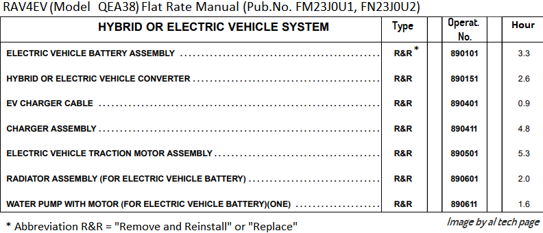
Yesterday, I replaced the contactors and installed a separate BMS mounting plate ground strap. These notes are for the next time I have to do this job.
I've found that much of electronics diagnostics is just looking at things. Tapioca on left, Butterscotch on right:

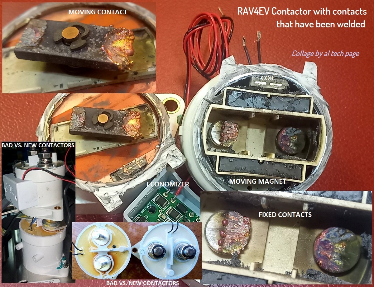
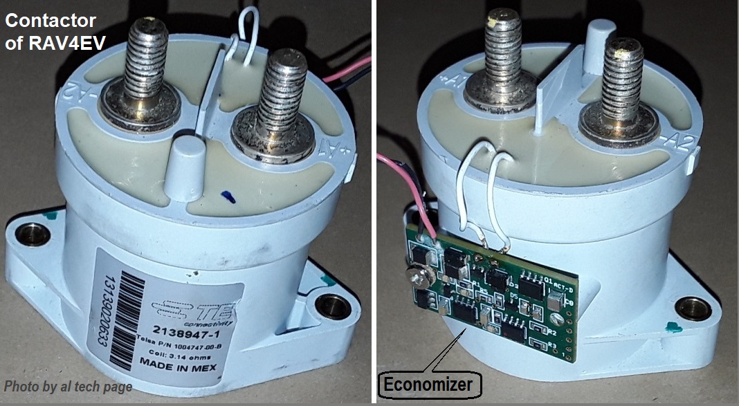
Interesting that the two contactors have different part Nos., though the contacts polarity is the same. Current-carrying contacts in the DC world
are polarized, and datasheets routinely warn of reduced contact life if the contacts are opened under load, and especially if the polarity is reversed and opened under load, which can sometimes occur.
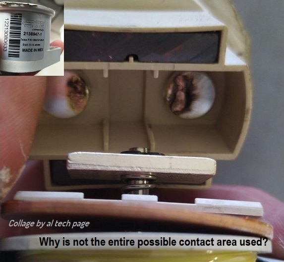
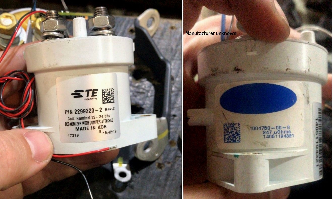
Passenger side: TE 2138947-1 (Tesla 1004747-00-B)
Driver's side:::::: TE 213894
8-1 (Tesla 10047
50-00-B)

Top view comparison with the GV200:

Before removing anything:

The copper laminate strap (insulated in orange, above) is flexible, but the other straps are aluminum and are not. This means that you have to (should) disconnect both ends of every aluminum strap to remove them, to R&R the contactors.
You kind of have to replace the Driver's side contactor first, because the Passenger side's output strap prevents removing or lifting the Driver's side's output strap far enough to remove the Driver's side contactor. Therefore, you can't finish the Passenger side until finishing the Driver's side. This is the order that I (eventually) used:

Mark the coils' wires' polarity first. I cut each wire one at a time, then slipped color heat-shrink up the harness and affixed it. If you do this one-at-a-time, it'll stay sorted. You could use tape or labels, too.
1 = 8mm
2 = 13mm
3 = T10
Lift out strap and remove completely.
4 = 8mm
5 = 13mm
Lift small strap
6 = T10
7 = Lift strap just far enough to clear contactor stud
8 = 13mm
9 = Remove orange shunt cover, then 13mm
Lift out strap
The Driver's side contactor can then be unbolted (8mm x2) and lifted out.

The Passenger side contactor is comparatively easier, as you've already removed the two hard straps, and the copper laminate strap is quite flexible and can be lifted an inch. You've already read above about the problem I encountered when attempting to remove that long ground strap from the corner of the battery, to ease removing the Passenger side contactor hold-down nut, so next time . . . I will probably attempt to remove that nut from the side, and leave that ground strap alone.
Better view of three of the four T10 screws. These thread into plastic, so be careful when tightening:

Contactors installed, aux. ground strap installed:


") in general, there are only two variations - buy on ebay for $ 50, or buy for $ 130 in Europe, but these are not bearings, it's easier with bearings, there is more choice
in general, there are only two variations - buy on ebay for $ 50, or buy for $ 130 in Europe, but these are not bearings, it's easier with bearings, there is more choice