Charging stopped due to system malfunction

Toyota Rav4 EV Forum

Help Support Toyota Rav4 EV Forum:

This site may earn a commission from merchant affiliate links, including eBay, Amazon, and others.
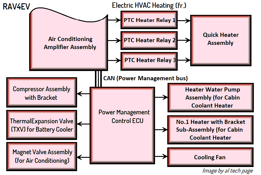
The PMC ECU also has control over the Pwr line, so it can in effect "reset" the heater if needed -- there are two relays and at least five fuses between Pwr and the heater.

As I'm not monitoring Pwr all the time, I wouldn't know that the PMC ECU cycles power to the LV side of the heater, but if you make your heater-side RMI voltage test using the same setup that I did, then you can compare results with some reasonable assuredness that the test results are relevant.
 
I repeat, ECU is disconnected from the pcb and test is performed on the heater pcb. 12v is connected to pwr on the pcb
The difference is not only in the absence of HV voltage.
1. The presence of external power supply of the PMC ECU is not enough to activate it/to control its output stages, such as current sources.
IMG_20241104_001940_309.jpg
https://alflash.com.ua/2019/to_rav4ev/heat_control.png
heat_control.png

2. Mr. asavage did not connected external resistors to the RMI.

Note. I don't claim to be the "ultimate truth", I only express my private opinion, analysis, experience, versions, recommendations.
 
Last edited:
Yes. It absolutely could matter. I have no idea of the interaction of the heater's LV circuitry with the HV; for all I know, the LV side goes into a limp mode or shutdown (or doesn't respond) if the HV side isn't ready for operation.
1. Part of the drivers for controlling the HV transistors of the heating elements is galvanically separated from its low-voltage part and from the heater control board.
2. The /FLT signal from this drivers is transmitted to cabin heater CPU when its internal circuits fail, but not due to the absence of HV voltage.
 
Last edited:
The difference is not only in the absence of HV voltage.
1. The presence of external power supply of the PMC ECU is not enough to activate it/to control its output stages, such as current sources.
The setup for this test is very similar to the NE555 pwm test that got the heater working, but voltage at rmi is tested under 3 conditions. The idea was not to activate the heater, but just to see the behavior at rmi pin.

I did 3 tests, open rmi and two more tests connecting through 2 resistances. I am fairly confident that the first test is equivalent to asavage's if my assumption that HV should not affect LV is true.

I can repeat the test under the exact same conditions as asavage's for a true apples to apples comparison.
 
Last edited:
The PMC ECU also has control over the Pwr line, so it can in effect "reset" the heater if needed -- there are two relays and at least five fuses between Pwr and the heater.

As I'm not monitoring Pwr all the time, I wouldn't know that the PMC ECU cycles power to the LV side of the heater, but if you make your heater-side RMI voltage test using the same setup that I did, then you can compare results with some reasonable assuredness that the test results are relevant.
I agree that there is a possibility but in most of my tests one of the probe is connected to pwr and I have never seen pwr being cycled at any point by the ECU.

Yes, I will repeat the test using the same method.
 
@asavage I am curious about how a good heater will behave in these two scenarios.

1. Does ecu provide pwm on rmi when it is open and d15 disconnected
2. When cabin heat is not requested, what's the voltage at rmi with d15 connected. Voltage at rmi is close to zero in all scenarios unless I use an external resistance
 
... 2. When cabin heat is not requested, what's the voltage at rmi with d15 connected. ...
Hmmm, at the 70th second of this video in https://www.myrav4ev.com/threads/charging-stopped-due-to-system-malfunction.2692/#post-31687
IMG_20241104_155615_478.jpg
an oscillogram of the RMI voltage (with d15 connected at good cabin heater) is shown when the target heating temperature is lower than the outside temperature. That is, when heating is not required.
Update.
rmi_check1.jpg
The difference in voltage can be explained, among other reasons, by the presence of a diode in the "feed" circuit of the input circuit.
 
Last edited:
That video was made a year ago to demonstrate how to check the cabin heater after repairing its control board. So I don't have an answer to your question.

I assume that when the cabin heating is turned off, RMI voltage will be as in the photo in my previous answer.
I repeat once again, I don't understand why the cabin heater works from the NE555 generator.
If possible and desired, repeat the test when controlled from this generator.
 
Last edited:
@asavage I am curious about how a good heater will behave in these two scenarios.

1. Does ecu provide pwm on rmi when it is open and d15 disconnected
2. When cabin heat is not requested, what's the voltage at rmi with d15 connected. Voltage at rmi is close to zero in all scenarios unless I use an external resistance
My current working theory is that the PMC ECU doesn't "provide" (source current) under any circumstance; it's a current sink only. D15 provides 12v nominal to the heater, the heater then sources a lesser voltage (~13.5 in my case), current limited, to the RMI line, and the PMC ECU sinks that current at a 40khz oscillation. That it appears as PWM doesn't mean it is, but it's certainly square wave. Vlad pointed out one instance on one of your vid clips of the PW changing. For example, at 54s of Vlad's vid:


As the target temperature is changed, the pulse width widens, and when target is acheived, the PMC ECU stops pulling down RMI altogether; the RMI line floats to ~13.5 again.

I have never measured any significant voltage at PMC ECU side of RMI with D15 disconnected. With RMI floating, the PMC ECU side is effectively dead of voltage, and the heater side is ~13.5v.

I cannot perform any further testing today, as the weather here is 50 MPH winds from the south and heavy rain through tomorrow.
 
Last edited:
The duty cycle of the RMI pulses changes depending on the required heating value and probably on the difference between the set and actual temperatures.
And the "brains" (CPU) of cabin heater convert its value into control signals for groups of heaters elements.
 
@alflash I tested again with the exact same setup as @asavage , voltage at RMI is close to zero.
Channel 2 is rmi and ch1 is disconnected.

Also checked the current passing thru ground. The numbers read from clamp meter 0.22A and using a regular multimeter 0.05A are vastly different. Not sure which is right
20241104_120213.jpg
 

Attachments

  • 20241104_113918.jpg
    20241104_113918.jpg
    3.6 MB
  • 20241104_113828.jpg
    20241104_113828.jpg
    3.5 MB
  • 20241104_113816.jpg
    20241104_113816.jpg
    4.2 MB
Last edited:
AFAIK, we're back to Saturday: "I would call this a failure on the heater PCB".

---

Clamp-on ammeters may give you a reading at very low currents, but unless they're designed for low currents, they're wildly inaccurate at the bottom end of their range. Many years ago I bought a BK Precision 316 milli-amp clamp meter for low current tracking (mostly for use in phantom current drains with a vehicle off), and it's much more accurate for this kind of work -- if you really need an accurate number. Usually, you don't. I see you're using the Zoyi's hardwire ammeter function, and I'd use that figure rather than the one from the TackLife clamp-on.

IMG_8647.jpgIMG_8650.jpgIMG_8646.jpg

It has a DC range of 1ma - 10A, with a rated accuracy of 2.5%, which is plenty for the stuff I do. The coil aperture is ~13mm. It works a lot better for small current detection than my larger units.
 
Last edited:
@alflash I tested again with the exact same setup as @asavage , voltage at RMI is close to zero.
Channel 2 is rmi and ch1 is disconnected.

Also checked the current passing thru ground. The numbers read from clamp meter 0.22A and using a regular multimeter 0.05A are vastly different. Not sure which is right...
1.
Measuring currents less than 1A with current clamps with a limit of 40A is a guarantee of inaccurate results.

In addition, it is imperative to perform a zero value calibration before measuring.
cur1.jpg


2. Illustration of a previously conducted checking (https://www.myrav4ev.com/threads/charging-stopped-due-to-system-malfunction.2692/page-11#post-32237)
inp.jpg
 
Last edited:
In addition, it is imperative to perform a zero value calibration before measuring.
Yes, I have been doing this.

Using some overly simplistic (and possibly ridiculous) assumptions, drew a circuit of the heater and solved the equations. (The open circuit
Resistance between RMI and gnd is 3.3 megaohm, so this diagram is true only when voltage is applied)
20241104_152406.jpg

What is the resistance between RMI to GND through ECU when RMI signal is pulled down? I estimate it to be 80 ohm.
20241104_163520.jpg20241104_163525.jpg20241104_164535.jpg

Current to ECU via RMI:
1. With external resistor = 0.058A.
2. Without external resistor = 0.041A

41% increase in current to ECU via the rmi pin.

Concerns with adding a low resistance external resistor:
1. 41% increase in current to ECU, but only when cabin heater is on.
2. The power dissipation in external resistor is about 0.35W which exceeds limit. Probably could connect resistors in parallel to mitigate it.

While it's hard to tell for certain, do you think operating with an external 350 ohm resistor would break the ECU in the long run, assuming the above numbers are approximately correct.
 
All of my careers -- around seven -- from a teenager to retirement, were in the service industry. I have ventured down redesign paths only when a design by others proved to be unsuitable (unreliable, insufficient, etc.), because early on I recognized my inadequate education in any particular field would eventually have me making poor enough guesses that my work was less reliable than the system I was attempting to upgrade.

Put another way: I don't patch a design that doesn't have a track record for unreliability. In terms of both time and money, the odds of a successful and better outcome than replacing the failed part with the same one are poor.

You're thinking about an external pullup resistor (network, due to TPD of a single) because you have seen that it worked: you were able to obtain heater operation and a reasonable waveform on the 'scope. But, you likely cannot see how the circuit is supposed to work when it's not broken, and diagramming modern circuits these days requires skills and techniques not required 30 years ago, when this stuff was built on a larger scale, not multi-layer, and datasheets were more plentiful (if on paper); ASICs were rare, and many designs echoed engineering sample setups. That's not the case in 2014/24.

You risk upstream damage to at least the PMC ECU. But you could save the cost of a replacement heater. That's a trade-off that I wouldn't make.

Our power was just cut, so I'll leave it there; I have to go down a server before the UPS batteries are depleted . . .
 
...2. Illustration of a previously conducted checking ...
View attachment 1135
1. As I can see from the structural diagram (datasheet of ATA6624) of the RMI signal receiver, a current source* is included in its input circuit.

2. In this case, it is more correct to determine the current through an external resistor using Ohm's law: I = Urch: Rch (3.38V: 1500 Ohm = 0.0023A).

3. For now, I don't exclude a possible malfunction of the circuit aka "Short Circuit and Overtemperature Protection" of the RMI (LIN) circuit.
IMG_20241105_104857_091.jpg

I hope that checking the board with a working heater will answer the question "who is to blame?"...
*
As Reference. https://www.electricaltechnology.org/2022/11/current-source.html/amp ,

https://en.m.wikipedia.org/wiki/Current_source#:~:text=A current source is an,of the voltage across it.&text=A current source is the,from a negative voltage supply.
Update.
Note. Functional Description of (ATA6624) Bus Pin (LIN)
A low-side driver with internal current limitation and thermal shutdown and an internal pull-up resistor compliant with the LIN 2.x specification are implemented. The allowed voltage range is between –27V and +40V. Reverse currents from the LIN bus to VS are suppressed, even in the event of GND shifts or battery disconnection. ...
 
Last edited:
Last edited:
I live in a town whose primary economic activity is driven by a military base; power outages rarely last for more than a few minutes, and I haven't needed either my inverter generator (EU6500is) nor my 3kw static 12vdc->120vac inverter for the past two years, though storms do cause power cuts to this island frequently.

I live under the "112" dot on the PSE Outage Map below. Power comes from off-island, from the north, so the further south you live, the longer your Winter power outages last. My mother lives near the southern end of the island, and loses power around a dozen times per Winter, sometimes for many days. She has an excellent remote-start inverter genset (another EU6500is, backed by many extra fuel tanks). This is kind of necessary if you have medical devices such as O² Concentrators and CPAP machines, as she does. I refuel her setup as needed. At 82, she no longer can lift the fuel cans, nor can she navigate the step into the barn easily while holding a flashlight.

IMG_9491.PNG
 
Put another way: I don't patch a design that doesn't have a track record for unreliability. In terms of both time and money, the odds of a successful and better outcome than replacing the failed part with the same one are poor.
I agree with that as a general rule of thumb to make decisions, but it is a bit complex in this particular case because of the following. @asavage Please correct me if I am mistaken in any of the points.
  1. The heaters themselves have persistent issues. Even a new one doesn't appear to provide the reliability we expect
  2. Cost of a new Rav4EV original heater assembly is absurd (20% of the value of the car), if at all available. I recall seeing a price of $2200 but I cant see it anymore when I lookup
  3. Workaround using the Nissan Leaf requires irreversible changes to the HV wiring that I wish to avoid if at all possible. Also, the wiring changes would be quite time intensive for noobs like me and I am not sure if I will save any more time doing this. Also, IMO, a new Nissan Leaf heater is still not worth the cost of $1100 as it is not a drop in replacement.
  4. A used leaf heater is at a price point that I may consider but there is no guarantee of reliability which makes this option worse than the external resistor hack in my opinion, after reading all the complaints about it.
  5. Since we don't have any way to determine what component may have failed, component repair is infeasible.

Worst case: ECU completely fails and all temp control is broken, rendering the car unusable.
Bad case: ECU fails and RMI control is broken which causes no heating from the non-PTC heater.
Best case: External resistor hack works and if it holds for a few winter seasons, we would have a viable hacky option to consider.

A few questions

1. To quantify the cost/impact of the bad/worst case, does anyone know the cost and complexity involved in replacing the ECU? I don't know what to search for
2. Does anyone know if the Nissan heater PCB fits into the Rav4ev heater PCB?
 
Back
Top