Introducing OVMS for RAV4 EV

Toyota Rav4 EV Forum

Help Support Toyota Rav4 EV Forum:

This site may earn a commission from merchant affiliate links, including eBay, Amazon, and others.

miimura

Well-known member
Joined
Jan 17, 2013
Messages
1,972
Location
Los Altos, CA
I have been working on a port of the OVMS system for the RAV4 EV. It is ready for people to start using it now. OVMS is short for Open Vehicle Monitoring System. It consists of a small box that connects to a vehicle and can report on its status. It was originally independently developed for the Tesla Roadster since Tesla didn't provide any remote connectivity for that vehicle. It is available as WiFi only or you can buy an optional 4G + GPS card that mounts inside the box. One reason that I haven't announced this earlier is that the 4G modem was just released. There wasn't much point for people to buy it with a 3G radio since those networks were going away soon anyway.

The current implementation is relatively limited. It only reads from the Tesla CAN bus, but we can display anything available on that bus. The next phase of the development will be to decode the Toyota CAN bus and replicate all the remote functionality that was available in Entune through the SafetyConnect communication module. Anyone who wants to help with that, please contact me.

One other cool thing that is available now is A Better Route Planner live data update. The OVMS reads the vehicle position, SOC, speed, battery charge and discharge power and uploads it to the ABRP servers. This gives you extremely accurate trip planning while en-route because it's adjusting to your battery level in real time.

The hardware costs $180 shipped from Asia including the 4G modem and requires a custom cable. It is relatively easy to use standard OBD connectors to pick up the Tesla bus from the connector at the rear of the car and inject 12V power from the nearby power outlet. However, we have identified the exact connector on the Gateway ECU and will offer a special cable to pull both the CAN buses and the always on 12V power from there and put it directly into the OVMS DB9 connector.

https://docs.openvehicles.com/en/latest/

The hardware is available from the US distributor, Medlock & Sons. Select "kit w/ SIM7600G" to get the module with the 4G modem.
https://medlockandsons.com/product/ovms-v3/

The Asian distributor sells without support and incurs substantial shipping time.
https://www.fasttech.com/products/1230/10000001/9747555
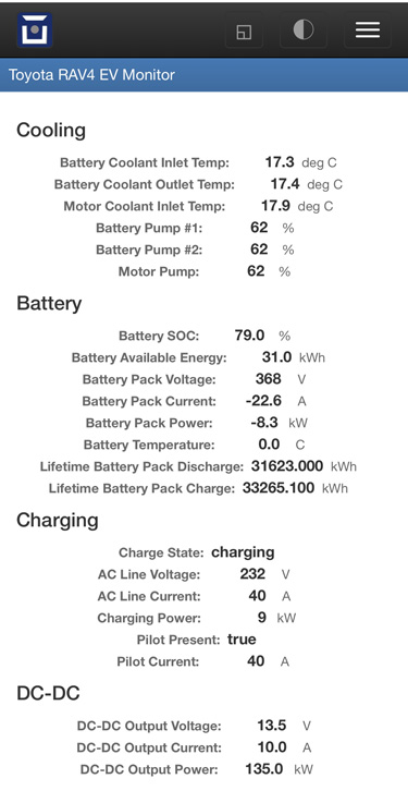
RAV4-Monitor-IMG-1322r.jpg

the typo indicating the DC-DC is outputting kW has already been fixed. It is now labeled "W". The battery temp is now displayed correctly too instead of the 0.0 shown above.
 
Great work! I've ordered the box and antenna from FastTech, as I'm currently moving house and have no time for the next month, so shipping delays are of no consequence.
we have identified the exact connector on the Gateway ECU and will offer a special cable to pull both the CAN buses and the always on 12V power from there and put it directly into the OVMS DB9 connector.
Will the availability of this cable (or data to source the connector + pinouts: I can build cables, given specs) be posted here? Or should I join an OVMS forum/list for that info?

I should have significant spare time from May-on, so I may be able to contribute then.
 
For anyone interested in making their own cable:

The male receptacle (e.g. on the gateway PCB) is only available as a PCB mount, so one has to solder flying leads to the pins (i.e. there is no option for male crimp pins). There are options for either straight or right angle:

https://www.mouser.com/ProductDetail/538-34690-9201 (straight)

https://www.mouser.com/ProductDetail/538-34691-0201 (right angle)

The female plug that will plug into the gateway's connector is either of these:

https://www.mouser.com/ProductDetail/538-34729-0201

https://www.mouser.com/ProductDetail/538-31408-1201

Both are listed as mating with the receptacles above, but I felt that the first option (-0201) fit slightly better than (-1201).

The female crimp terminals can be bought individually:

https://www.mouser.com/ProductDetail/Molex/34803-3212-Loose-Piece?qs=sGAEpiMZZMvlX3nhDDO4APA0O3OWFUmccAXmsdK26Xc%3D

Note these are intended for 20 AWG wire (other sizes are available if needed).

To make your own passthrough cable, wire receptacle-to-plug the following pins:

6 - IGCT
16 - IGDI
20 - B+
10 - GND

Use twisted pair for the following:
3 - Tesla CAN L
13 - Tesla CAN H

2 - Toyota CAN L
12 - Toyota CAN H

Optional: Ethernet port (only needed if using Tesla Powertrain software, such as Vlad's remote diagnostic support)
9 - TX+
19 - TX-
8 - RX+
18 - RX-

The OVMS module connects with a standard 9-pin d-sub; male pins are on the OVMS, so the adapter cable will be female sockets:

9 - 12V (B+)
3 - GND

7 - CAN0 H (Tesla CAN)
2 - CAN0 L

5 - CAN1 H (Toyota CAN)
4 - CAN1 L

The B+ and GND wires will tie to the corresponding pins on the passthrough cable constructed above. The two CAN connections should each be twisted as pair, and will similarly be connected in parallel to the corresponding pins.

If there is sufficient interest, I would be willing a) to make cables, and/or b) lay out a small PCB to go with the soldered-in connector, possibly packed in a small plastic box for a more robust interfacing solution.
 
Thanks for info.
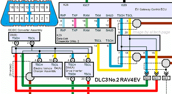
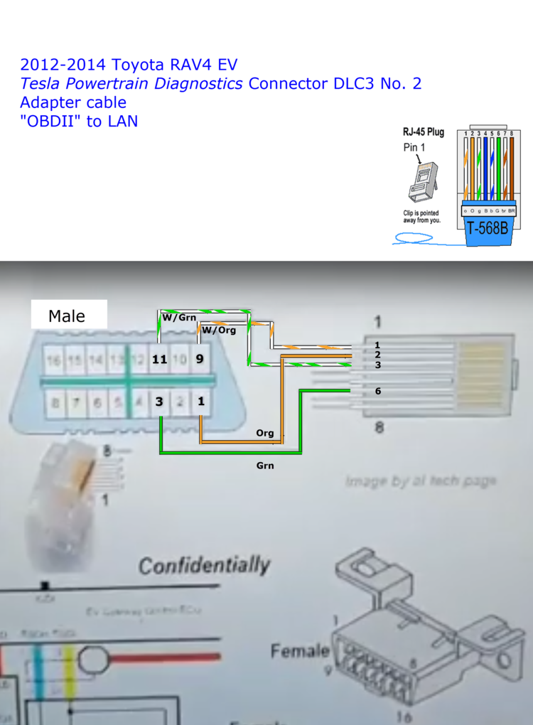
That k28 (gray) connector also has pin #7 aka SHLD (pin #12 of Data Link Connector 3 No. 2)
DLC3no2rav4ev.gif
 
asavage said:
I'm hopeful that miimura will respond to my questions of 25Mar, as I can't collaborate without communication. But, yes, I'm holding the hardware + 4G antenna: the easy part.

Matt provided the detailed cable information above. All of my current code is checked into the master branch on GitHub, but you probably need to sign up for "edge" firmware update from their servers in order for my code to be included. I normally update my module over my local wifi. I just turned on IIS on my desktop windows box and put the locally compiled binary in a folder under the webroot.

Since Toyota is totally incapable of restoring Entune communication with my car, we need people that can capture CAN logs while issuing remote commands that go through SafetyConnect. By capturing the Toyota CAN bus when the telematics module is passing information to the car, we can replicate that functionality.

Anyone who wants to communicate directly about this project can send me a Private Message on this board and I will provide my e-mail address.
 
Good work, Matt.

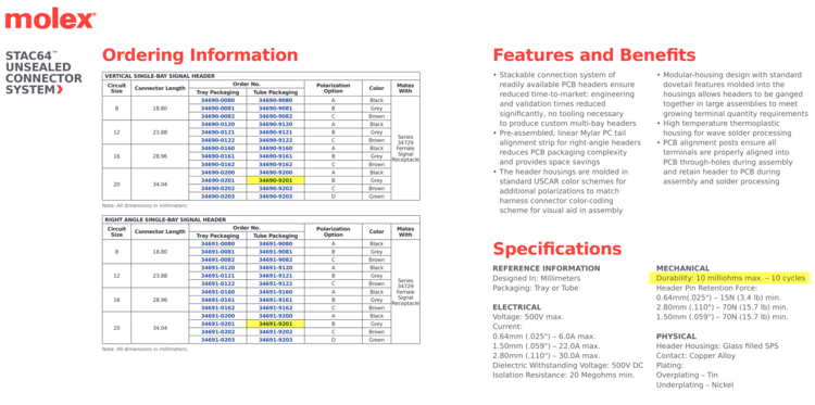
Hmmm, only ten connect/disconnect cycles max, ouch:


https://www.content.molex.com/dxdam/literature/987651-0951.pdf, pg. 11

Good thing I'm not planning to install/remove this much.

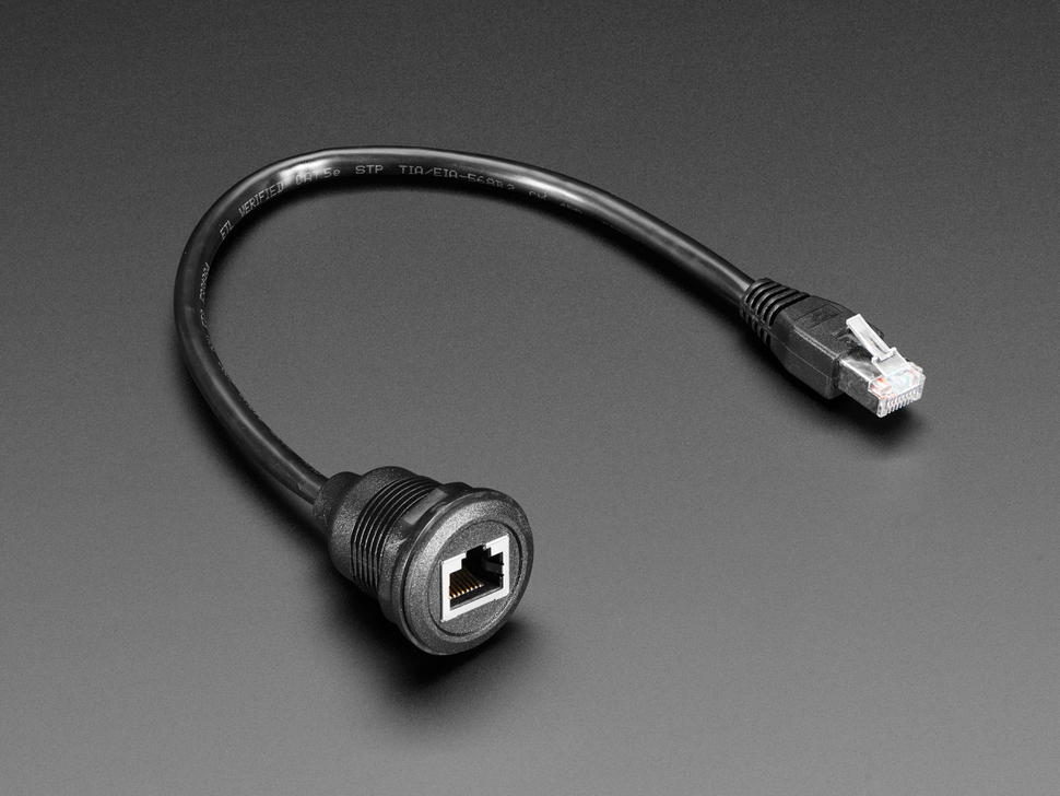
To simplify the Ethernet connection, I've ordered a RJ-45 Ethernet Round Panel Mount Extension Cable, Adafruit 4215, $5 from Adafruit or Mouser, and I'll cut off the plug. (For those who prefer, naturally there's a similar product at Amazon)

Connector_Harness_Ethernet_8P8C_RJ45_Adafruit_4215-02_01b.jpg


On the CAN connections: my understanding is the Best Practice is to have terminating resistors at either end of the physical bus, and that intermediate CAN devices should pass through the lines. I'm reading that any stub connections should be kept short, and that they have the potential to reflect the signal. Does anyone know if the OVMS incorporates termination? I'm assuming it's not needed, but then again I don't know a lot.


I was going to chop up a spare serial cable from days gone by, but the first two I pulled out of the bin didn't have all wires through, and then I saw, "The two CAN connections should each be twisted as pair," and realized I'd have to run wire anyway, so gave up on chopping a cable up for this. In a previous life I used to repair computer monitors and terminals, and a common failure was when people shoved their CRT monitor away from them and the signal cable, which often exited the rear of the monitor horizontal, would be forced to a 90* bend, eventually breaking one of the signal pins. I say this to note that I'm certain that I do have a couple of DB9 (DE9) backshells in my stock, but those bins are not only in storage, they're tied face-to-face to prevent the sliding drawers from increasing entropy, and it's literally not worth $5 for me to untie/retie them right now . . . so, I thought I'd add one to the Mouser order I'm compiling. Wow, the metal backshells have gotten expensive (metal is all I'll use, too many stripped or warped plastic shells in my past). Mouser TE Conn. 571-5748676-1, $9. Ouch. Part of living a while is you get to see prices move.

The actual DE9 connector, Mouser Amphenol DE09S064TLF with female sockets and easy-to-assemble solder cups, $0.67 ea.

The OVMS I purchased is supplied without a SIM card (or data plan), so signed up with Hologram.io and added a form factor 4FF-compliant Hologram.io SIM card to my Mouser order, SIM-E-TRI-GL, $4. Once I get the SIM, I can register it with Hologram.io and it'll become active (I hope; I've never done this before, everyone's new at things once).
 
The Tesla and Toyota CAN networks are terminated at both ends. A brief scan through the OVMS documentation seems to indicate that there are no termination resistors in the unit, so it should connect without any problems.

The max length for a CAN stub is 1 meter, but I recommend keeping it as short as practical. For the twisted pair, you can make your own or I often recycle twisted pair from old Ethernet cables.
 
I don't see any utility in bringing out the Ethernet from the Gateway. My understanding is that everything on there is also on the CAN buses. The only utility is if you want to remote connect with "our friend in Ukraine".

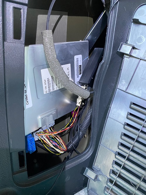
I don't completely discount the need for termination since I occasionally see some slight weirdness in my keyless entry when anything is plugged into the Toyota bus. However, the stub going to the OVMS is only a couple inches long. I may look at it with an oscilloscope if there are accessible probe points on the OVMS board. There is also a metal "saddle" that nicely supports the OVMS box next to the Gateway.

Gateway-OVMS.jpg
 
I'd like to eventually get Tesla Powertrain Diagnostics working -- my cracked copy says it's licensed, but will not talk to the Gateway via my cable, and I've checked that cable a dozen times, can read the Gateway's MAC on my diag. laptop using it, so I'm at a standstill -- and while I can jack into the DLC3-2 connector, i think there's utility to be had in using a dedicated 8P8C port. But, yeah, it's not necessary.

The twisted pair twist spacing on run-of-the-mill LAN cabling is optimized for ethernet frequencies, but I assume it's adequate for CAN bus use. Certainly, I've enough of it laying around, probably still have 1/3 of a 500' spool kicking around somewhere, I ran a lot of hardwire in this house.

(KiCad is giving me fits today, really bumming me out with their install script problems and packaging errors
later: got it. Uninstalling doesn't wipe ~/.config/kicad , whick keeps track of the symbols library. Ugh. Every reinstall gave the same errors, because the installer made assumptions.)
 
alflash has a cable specification that he regularly uses to perform remote diagnostics. It's pretty simple and if you're reading the MAC address then I suspect that you already have one that should work. But if you want to test it, you can contact him via his website, alflash.com.ua
 
I built the cable using Vlad's wiring diagram:


Even though he's got RX<->RX and TX<->TX, which is not a good look, modern ethernet hardware drivers do RX/TX swap on-the-fly, so it works for us -- I'm old enough to have had to deal with dedicated or manually switched LAN ports on routing equipment. But, yeah, I can read the Gateway's MAC, so my cable's working. I'm thinking I've got a bad crack, but these things happen, and getting it sorted hasn't been at the top of my list for a while.

[later]
I was able to get TPD working. It was a software problem, not the cable.
 
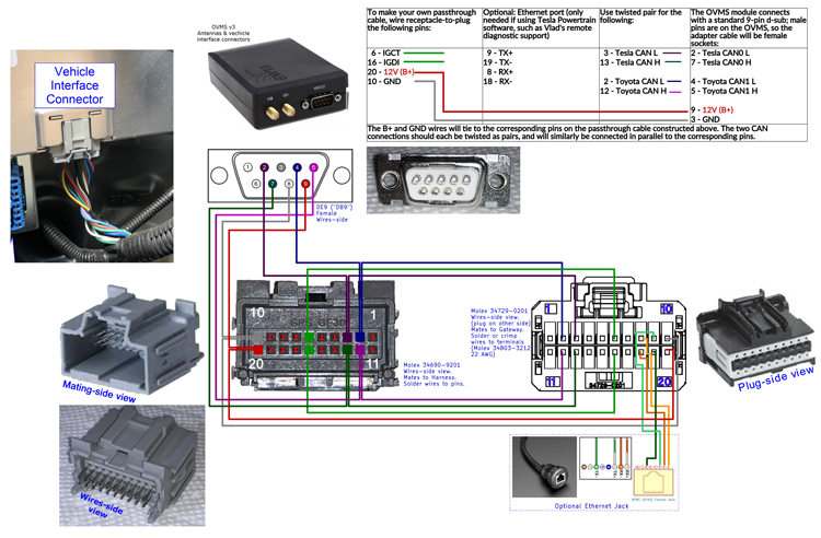
My parts won't arrive until Thursday night, so . . . first pass at a wiring diagram. I should've used a different tool, and I'm not 100% happy with the rendering, but it's a first attempt.

I like this kind of visual guide when building harnesses; other harness builders use different methods.

Click on the image to get a larger, more detailed version, but be patient: it'll take a while to load.


Older version(s):
04May2022
04May2022
04May2022
04May2022
03May2022
29Apr2022
29Apr2022


---

Matt, I'll be interested in a one-box build of this, with the optional 8P8C jack, should you get enough interest. I'll build this with discrete parts, tape, and epoxy, for a working interface, but long-term this should all be in a box with a short cable to the Gateway, and possibly another short cable to the OVMS (or a DE9 for a user-selectable-length cable to the OVMS).
 
I think you have the Ethernet connected to the wrong side. My understanding is that the Ethernet is coming out of the gateway on its way to the blue DLC3 connector. I think if you wire it as shown, there won't be any link, you will just be wired to the normally empty blue DLC3 connector.
 
Al- I am interpreting your description of the connector (-9201) that plugs into the harness "from the wire side" to mean looking at the back side of the connector where you will solder leads to; if that's the case, then your pin numbers needed to be mirrored to match the gateway connector (which appears correct, assuming the leads are coming out of the screen). Presently the pin numbers on -9201 as shown are correct only when viewing the connector from the front, looking down at the male mating pins (tiny pins numbers stamped in the plastic are visible in this view).

Also, Mike is correct about needing to move the Ethernet cable over to the gateway connector.
 
Good catch, Mike! Yeah, connecting the LAN jack to the Toyota's harness wouldn't likely get me very far.

Good catch, Matt! I'm used to seeing the mfgr's pin numbering on the back of the shell, and for some reason I got stuck on those drawings being the rear, not the mating side. It doesn't help that Molex gives pages of tables of specs but won't annotate the line drawings. I'm sure people who do this a lot more than I "just know" which end is up.

Scroll back and take a look at the image again; I've updated it. I've also provided a link to the previous one.
 
Thanks! Fixed. Also fixed was a missing TX- wire that was somehow deleted during previous editing.

Ugh. How do you know these things? I can't tell visually, and I've read hundreds of drawings and got paid to do it ;)
 
Back
Top