DI_f108 doesn't have any Google hits, but if the Gateway thinks that the brake pedal is depressed, that's going to be a problem. I know you've checked that the physical brake lights are toggling correctly, but TPD is saying something else.

You are using an out of date browser. It may not display this or other websites correctly.
You should upgrade or use an alternative browser.
You should upgrade or use an alternative browser.
Errors After Inverter control board replacement and problems with re-flash.
- Thread starter Arlin
- Start date


Help Support Toyota Rav4 EV Forum:
This site may earn a commission from merchant affiliate
links, including eBay, Amazon, and others.
Arlin
Well-known member
As soon as I shift into gear I get the drive fault on the inverter.
TPD reports an Alert, but it's not saying the inverter is the cause. It's in a faulted state. Brake is ON, speed sensor data is ???
You disconnected the speed sensor and TPD reported a different Alert, but speed sensors are known to fail in non-obvious ways. See this thread, for example.
You could scope the sensor lines, if you have a reasonable idea of what waveform you should be seeing, or you could obtain a known-good speed sensor and swap. New ones from Toyota are around US$300 now Or, you could play parts quality roulette and pick up a $55 Chinese knock-off via eBay.
You disconnected the speed sensor and TPD reported a different Alert, but speed sensors are known to fail in non-obvious ways. See this thread, for example.
You could scope the sensor lines, if you have a reasonable idea of what waveform you should be seeing, or you could obtain a known-good speed sensor and swap. New ones from Toyota are around US$300 now
Or, you could play parts quality roulette and pick up a $55 Chinese knock-off via eBay.Arlin
Well-known member
I have two speed sensors. Both the same fault. I can see what it looks like. But the motor never moves at all. Just instant fault.
IMHO.The inverter does NOT see the rotation of the rotor and, according to Tesla’s stupid logic, writes about a sensor failure. Although the reason may be, for example, a jammed rotor.
In my practice, I have repeatedly encountered cases where, due to the immobility of the rotor, there was a problem with the motor speed sensor. However, the sensor itself was fine.
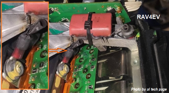
In one case (2020), only after the third (!) removal of the motor did the contractor discover some kind of loose connector in the inverter.
In another case (2019), the cause of the failure was a poor bolted electrical connection. After duplicating it with the help of an additional wire, the car drove
https://alflash.com.ua/2019/to_rav4ev/07s.jpg.
I wonder if this capacitor is working (photo https://alflash.com.ua/2019/to_rav4ev/inv_malf.jpg).
I do not insist on such possible causes of your car’s problem, but simply draw your attention to the fact that Tesla’s newcomers to diagnostics have written a very “stupid” self-test program for checking the state of electronic components and sensors of their powertrain control system.
Just for the presence of undocumented codes _w115 and/or _w023 they should have been fired without benefits... And for the absence of hardware configuration in TPD v1.1.46, they should have been fined for dishonesty!
The reason for the appearance of fault codes for the HVIL system remains unclear...
What exactly/specifically was the cause of those fault codes for the HVIL system?
Last edited:
Arlin
Well-known member
The HVIL in my case, was a bad connection from the connector on the control board. (I had repaired this.) And this was what Pins 7/8 were connecting to.The reason for the appearance of fault codes for the HVIL system remains unclear...
What exactly/specifically was the cause of those fault codes for the HVIL system?

$16.06
$16.91
MICTUNING Upgraded Dual USB Port 6.4A QC3.0 Quick Charger with Blue LED Digital Voltmeter Replacement for Toyota, Compatible with Cellphone iPad PDA Laptop GPS (Surface Size 1.6 x 0.9 inches)
Nado Stuff (Authorized Dealer)


$80.04
$84.00
Toyota Genuine All-Weather Floor Mats for 2007-2012 Rav4-Set of 4, New, OEM,
Lewis Toyota


Arlin
Well-known member
Yes I think something is up that during the self test it is not happy. I will post some pictures later. So its not that there is a speed sensor problem its that the system is not able to see the rotor move.
Is the rotor trying to rotate?Yes I think something is up that during the self test it is not happy. I will post some pictures later. So its not that there is a speed sensor problem its that the system is not able to see the rotor move.
I do not rule out that the inverter either cannot or does not want to control it, but the TPD diagnostic program either does not know or does not report this.
Arlin
Well-known member
See I don't know if it's trying to rotate. How do you tell??
Since the Motor Speed Sensor is designed to detects the motor speed and outputs the motor speed signal to the drive inverter ECU of the electric vehicle traction motor assembly, I would try to compare the voltage oscillograms of its contacts when the vehicle is stationary and when both front wheels are forced to rotate.
https://alflash.com.ua/2019/to_rav4ev/mss2.png
https://alflash.com.ua/2019/to_rav4ev/mss2.png
Arlin
Well-known member
I will do that next.Since the Motor Speed Sensor is designed to detects the motor speed and outputs the motor speed signal to the drive inverter ECU of the electric vehicle traction motor assembly, I would try to compare the voltage oscillograms of its contacts when the vehicle is stationary and when both front wheels are forced to rotate.
https://alflash.com.ua/2019/to_rav4ev/mss2.png
You are saying measure/scope the wires going to the speed sensor that gets wet when the coolant seal fails?
I was thinking maybe the control board is looking at the rotating AC field and is looking at if the field is rotating and sending some info back saying the field is not rotating?
Arlin
Well-known member
I bet it's a problem on this connector. It's the one I had problems with for the HVIL. I have some +1.75 glasses now and it's helping me see better
Arlin
Well-known member
I had to clean off the silicone I put on it to protect it ...I bet it's a problem on this connector. It's the one I had problems with for the HVIL. I have some +1.75 glasses now and it's helping me see better
Attachments


Arlin
Well-known member


Note. I have never stated that the problem with your vehivle is a bad sensor connector or sensor wires.
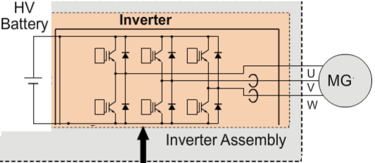
I was just reminding you that the stupid logic of Tesla’s developers is, as we saw on your car, apparently that due to the lack of a signal about rotor rotation, the inverter ECU considers its rotation speed sensor to be to blame.
And as a result, the system transfers the contactors from the open state to the precharge state, after which to the closed state, but probably due to the immobility of the rotor/lack of a signal about its rotation, the opening state follows, which ends with their open state.
One possible reason, but NOT the only one, is, for example, a jammed rotor.
The contact numbers of the inverter connector are known and it is possible to check the passage of speed sensor signals to the “brains” of the inverter after restoring its printed circuit board.
In addition, you can try to simulate the rotor rotation signal by moving a screwdriver near the sensor in both directions... Just a guess, It cannot yet be ruled out that this sensor is an MRE type, such as the 2-pin wheel speed sensors of this vehicle.
As soon as I shift into gear I get the drive fault on the inverter.
If his foot is on the the brake, in theory there is almost no movement of the rotor, and I would not expect a non-moving rotor to trigger a fault.
Why check for rotor movement?
Almost certainly, while the brake pedal is pressed, the inverter does not supply voltage to the motor. Or, knowing that the brake pedal is pressed, does not expect a signal about rotor rotation...If his foot is on the the brake, in theory there is almost no movement of the rotor, and I would not expect a non-moving rotor to trigger a fault.
Why check for rotor movement?
It is not for nothing that there are two sensors installed on the brake pedal.
*11 Brake Pedal Stroke Sensor Assembly
*12 Stop Light Switch Assembly
Attachments

Last edited:
Leaving aside CAN communication, I only see one connection from the brake switch to the LDU.
In the "Tesla only" annotated wiring diagram I put developed last year, I have labelled the brake switch simply a block element "Stop Light Switch":
_02-1b.png")
The fuller (less simplified) wiring:

The above is Powertrain wiring, and ancillary systems such as Lighting were not included here by Toyota; they are in a separate diagram:

In the case of the portion of the Stop Switch that operates the physical lights, output is on terminal 1.
But, for the LDU, signals (levels are unknown) are on terminals 3 & 5.
This, it looks possible for the Stop Switch to properly operate the stop lights but not offer the correct signaling for the LDU.
In the "Tesla only" annotated wiring diagram I put developed last year, I have labelled the brake switch simply a block element "Stop Light Switch":
The fuller (less simplified) wiring:
The above is Powertrain wiring, and ancillary systems such as Lighting were not included here by Toyota; they are in a separate diagram:
In the case of the portion of the Stop Switch that operates the physical lights, output is on terminal 1.
But, for the LDU, signals (levels are unknown) are on terminals 3 & 5.
This, it looks possible for the Stop Switch to properly operate the stop lights but not offer the correct signaling for the LDU.
Do you think that the Stroke Sensor could send garbage data to the LDU via the Gateway that could inhibit drive? I would think not: coasting downhill and applying brakes is not abnormal.It is not for nothing that there are two sensors installed on the brake pedal.
*11 Brake Pedal Stroke Sensor Assembly
*12 Stop Light Switch Assembly
Arlin
Well-known member
Just got the motor running. Man or man!!! I will write up all of the details to help others..
Wow!Just got the motor running. Man or man!!! I will write up all of the details to help others..
The speed sensor was fine???
It seems to me that it would be very useful and interesting to see oscillograms of signals/voltages on all four contacts of the rotor speed sensor...
Last edited:
Similar threads
- Replies
- 39
- Views
- 6K
- Replies
- 17
- Views
- 8K
- Replies
- 16
- Views
- 20K