(di_w020 / di_f020)

Toyota Rav4 EV Forum

Help Support Toyota Rav4 EV Forum:

This site may earn a commission from merchant affiliate links, including eBay, Amazon, and others.

ogmm

Member
Joined
May 9, 2019
Messages
20
Location
Guatemala
I bought 3 encoders(revision C from china, the orignal is revision B) but still getting the speed sensor errors. Checked the wiring from the sensor to the inverter conector and it is ok.

The motor rotates normal but in a random time it stop rotating(before was every 15-30min now is 3 to 8 min) and shows the speed sensor issue, if i shutdown the car and put it in drive it works even with the error showing but again stop working in a few minutes. Also uploaded the gateway firmware trying to fix this.

I'll try to check with the osciloscope the encoder signals just to confirm that the old and new encoders are ok.

What do you think what could be? Any insight will be appreciated.
 

Attachments

  • 1717775588981.png
    1717775588981.png
    104.4 KB
Hi,

After checking this post, thanks to Volodimir Leshchenko. Besides the continuity check was ok on the connector. I have soldered the connector on the main board of the inverter . Then I partialy assambled the drivetrain and it worked without any issue for 45min of testing. Right now I'm waiting for LDU coolant cap and drive shaft seals to complete the assambly of the car and get it completly testing.

I'll posting the results after receiving the parts and test, about 2 weeks from now.

WhatsApp Image 2024-10-09 at 9.21.53 AM (1).jpeg
 
Bad news, i was just trying to see if it still working while waiting for the parts i had order, but now the error just pop out within 30 seconds after left the brake pedal.
I had to disassamble the motor again and pulled back the board, i had checked continuity but still ok, so i will remove completly the connector clean all the pads and weld again the connector back. I'll post again the result.
 
Hi, i have removed the connector, the varnish is very difficult to remove. I hope to test this weeked, the parts i ordered have not yet arrived. I'll keep you posted.
 

Attachments

  • WhatsApp Image 2024-10-30 at 10.05.43 AM.jpeg
    WhatsApp Image 2024-10-30 at 10.05.43 AM.jpeg
    1 MB
Hi,
I finally received the parts, coolant delete cap and driveshaft seals, coolant cap installed following this video.

Unfortunately removing and re-soldering the connector did not work. It worked perfectly the first time for an hour switching from D to B and reverse but the next day it worked fine for about 10 minutes and the same error again.

I am not sure if there is another faulty soldering on another component or if there is some kind of reset when I leave it without 12v for a long time and it works fine the first time. I am wondering if replacing the main board with this one on eBay and reflashing it with the tool will fix this problem. This board is very expensive for me, US$550 and I don't want to spend this amount if I am not sure if it will work for sure.

In the meantime I am leaving the car without 12v just to check if this is the reason it worked fine the first time.

Any feedback will be greatly appreciated.
 
...
Any feedback will be greatly appreciated.
Can you check the signal/voltage passage between connectors D1 (speed sensor) and D14 (drive inverter)
https://www.myrav4ev.com/threads/charging-stopped-due-to-system-malfunction.2692/page-5#post-32002 ?

Voltage on D1 connector (https://www.myrav4ev.com/threads/charging-stopped-due-to-system-malfunction.2692/page-6#post-32033 ) ?
For example, with an oscilloscope, as shown in https://www.myrav4ev.com/threads/charging-stopped-due-to-system-malfunction.2692/page-6#post-32085 ?
with forced rotation of wheels (rotor).

Note. "Shaking" the thermometer, as well as long-term disconnection of the 12V battery, has very little effect on the health of the "patient" ...
 
Last edited:
Hi,
I wanted to tell you that something unusual happened. I left the 12V battery disconnected and connected it again yesterday. At first, it worked for a few minutes and then stopped, so the 12v reset didn't work. I decided to measure the sensor, and although I don't have an oscilloscope, I measured one side, rotated, measured again and repeated the process. The voltage on each channel was at 5v and then dropped when turning the shaft; it seemed that the sensor was fine.

Then I thought about measuring it in motion, since it is a square signal, it should show approximately half the voltage on each channel while it is running, and indeed it was around 2.5V on each channel. Before turning it on for the test in motion, I decided to push the low voltage connector of the inverter (where the signal from this sensor comes in) to make sure there was no false contact. The second time I turned it on after moving the connector, it worked for two hours. I turned it off, turned it back on, and it worked fine for another 10 minutes; I turned it off, turned it back on, and it worked for 20 minutes.

I tried it this morning, and it failed after 3 minutes. I pushed the connector back in, and it's been working for about 45 minutes now.

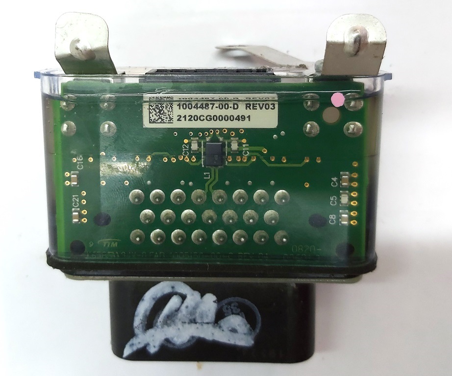
I think it might be a problem with one of these two connectors or the wire that goes to them. I had previously checked the internal connector, and although the solder joints looked bad, and I got a bad continuity reading at first, when I tried to confirm the bad continuity, it no longer showed continuity faults, so I ruled out that it was bad. Also, since the connector is covered in a transparent soft gel, re-soldering it is not easy, so I assumed it was good.

Long story short, sensor voltages are ok, i suspect the connector on the image is bad. Even on this image that is for an item on sale the welds looks extremly bad.
1004487_00_D_NC_%D0%A0%D0%B0%D0%B7%D1%8A%D1%91%D0%BC_%D0%BD%D0%B8%D0%B7%D0%BA%D0%BE%D0%B2%D0%BE%D0%BB%D1%8C%D1%82%D0%BD%D1%8B%D0%B9_%D0%B8%D0%BD%D0%B2%D0%B5%D1%80%D1%82%D0%BE%D1%80%D0%B0_%D0%B1%D0%BE%D0%BB%D1%8C%D1%88_%D0%BC%D0%BE%D1%82%D0%BE%D1%80_REV03_Tesla_model_S_S_REST_1004487_00_D_1.jpg
 
Back
Top