ALL POSTS - Heater Failed - Service Bulletin TSB 0111-14

Toyota Rav4 EV Forum

Help Support Toyota Rav4 EV Forum:

This site may earn a commission from merchant affiliate links, including eBay, Amazon, and others.
Thanks for clarification!
As another heater failure - this Rav has actually had the heater fail twice - once dc-dc was taken out - once not.
On the failure that included dc-dc converter - my recall was it was working then not working -p no slow fail.
On my failure that didn't take out dc-dc - it was a slow burn - would stat up and then fade during my drive.
 
Upon opening, I can confirm with 100% certainty the smell I detected matches that inside the heater. Also, the button is a vent that equalizes the heater case to the atmosphere… I pushed through the hydrophobic media to confirm it’s a clear opening.

Any obvious electrical failures to be seen? Wondering if it might something as simple as a diode or FET that could be replaced...
 
Any obvious electrical failures to be seen? Wondering if it might something as simple as a diode or FET that could be replaced...

The heater is basically the same as the one used on the very early 2011-2013 Nissan Leaf, and here's a short/decent rant about its faults: https://ev-olution.yolasite.com/Nissan-Leaf-Heater-Fault.php

1706810656988.png

1706810668051.png

1706810677575.png

No real repair info there, but based on the pics they took, plus the smell reported by ph2, there's probably fried stuff, sure. Is it repairable? Maybe. Depends on what your time is worth and your tolerance for risk. If it's "lightly fried" and damage is limited to a couple of components, and a suitable replacement MOSFET or two can be obtained . . . maybe.

Matt, you or I might try a repair because we've done this stuff for a living, but for the majority of RAV4 EV owners, I wouldn't recommend trying.
 
Any obvious electrical failures to be seen? Wondering if it might something as simple as a diode or FET that could be replaced...
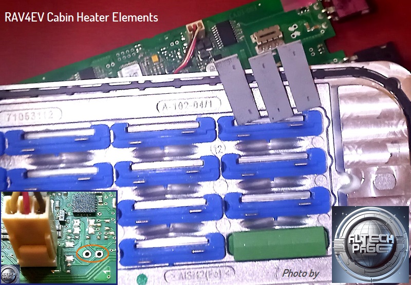
Hi All, still working on it… didn’t start looking until yesterday. Very similar to the Leaf heater in the photos above but a few differences.
Instead of the PCB for the connection to the heat elements it uses a stamped silver sheet with teeth.
IMG_0163.jpeg
Notice the green rubber piece filler… bet that is filled with an element in the 6.3kW version. Works out to about 400 watts for each element inserted.
The IGBTs are readily (for now at least) available if that is what fails on your heater, International Rectifier AUIRG4PH50S. It would likely take a lot of other things with it.
Will post more when I find something, but not immediately obvious which leads me to believe one of the ICs has failed… which would make sense in the slow fail scenario vs an IGBT which takes the DC converter fuses with it.
 
Hi All, still working on it… didn’t start looking until yesterday. Very similar to the Leaf heater in the photos above but a few differences.
Instead of the PCB for the connection to the heat elements it uses a stamped silver sheet with teeth.
.
Notice the green rubber piece filler… bet that is filled with an element in the 6.3kW version. Works out to about 400 watts for each element inserted.
The IGBTs are readily (for now at least) available if that is what fails on your heater, International Rectifier AUIRG4PH50S. It would likely take a lot of other things with it.
Will post more when I find something, but not immediately obvious which leads me to believe one of the ICs has failed… which would make sense in the slow fail scenario vs an IGBT which takes the DC converter fuses with it.
As far as I remember, there are two connectors on the Leaf heater control board. On the same board (photo) by RAV4EV, its place is empty.
Photo of your heater's printed circuit board from the component installation side?

Does anyone have a datasheet for these types of cabin heater heating elements?
heat_elem_fr.jpg
https://alflash.com.ua/2019/to_rav4ev/heat_elem_fr.jpgFor example, Resistance vs. Temperature and other parameters.
 
Last edited:
I am finally ready to start on this heater replacement project - I have both a brand new Rav heater as well as a used leaf and ford heater.
But first I want to test the dc-dc fuse and I want to ask if I need to disconnec the 12 volt battery completely or just the negative side?
 
I am finally ready to start on this heater replacement project - I have both a brand new Rav heater as well as a used leaf and ford heater.
But first I want to test the dc-dc fuse and I want to ask if I need to disconnec the 12 volt battery completely or just the negative side?
Removing the battery will give you a bit more room to navigate under the hood, but removing the positive or negative side will do the trick. Make sure it won’t slip back towards the post. Then remove the HV disconnect under the passenger seat as a safety. The TSB will walk you through the test procedure.
 
Electrically, it doesn't matter which terminal you disconnect.

For safety, the generic advice is to connect the negative terminal last and disconnect it first. I won't go into details, but there were valid reasons why that was the way we were taught back in the day, so it's habit for me. But the car doesn't care.

And ph's advice is good: wrap the cable that you disconnect in a rag. The cables are stiff and have memory and want to return to the battery -- they long for completion. Left alone, they will creep back toward the terminal they were removed from. So put a condom on the cable: wrap it in a rag.

Or remove the battery from the car.
 
Well I was always taught to do the same with positive and negative cables - and I wrapped them as soon as disconnected.

Now the good news - the DC-DC path has full continuity - so thats awespme - I was pretty sure it was good but you never know.

No continuity on heater - which was expected.
Next up - dig up what to remove on JDemo and replace the heater - then I would like to open up the dead heater and do the other tests you guys have pointed out.
Then before I wrap everything up I am going to use the bad heater cables and make a backup heater using the ford heater so I have it.

Might even install Tony's coolant delete mod while I am garaged.
 
Electrically, it doesn't matter which terminal you disconnect.

For safety, the generic advice is to connect the negative terminal last and disconnect it first. I won't go into details, but there were valid reasons why that was the way we were taught back in the day, so it's habit for me. But the car doesn't care.

And ph's advice is good: wrap the cable that you disconnect in a rag. The cables are stiff and have memory and want to return to the battery -- they long for completion. Left alone, they will creep back toward the terminal they were removed from. So put a condom on the cable: wrap it in a rag.

Or remove the battery from the car.
The part about positive first / negative last applies to attaching jumper cables, from what I recall of my ICE days.

When one has a wrench on a negative terminal cable clamp, if the wrench contacts a body part or frame that is grounded, nothing happens. That's the reason for removing only the negative cable when disengaging the 12v battery in any vehicle.

When one has a wrench on the positive terminal cable clamp and it contacts a frame or body part, the entire power of the battery is available to turn the wrench into plasma. This is the rationale to save one's posterior while working on a 12v battery. (The linked story states that it was a brass connecting bar, folklore says it's a wrench.)

This is confirmed by Car & Driver, step 4, Autozone, step 2 and plenty of other online resources.
 
OK - Need some help - as I pulled the JDemo frame away I noticed the remnants of mice below - I removed the Jdemo inlet and found this. I am pretty sure this is the PTC heater pump as one hose goes to the PTC heater. I have not yet removed the heater - Is it possible that this is the cause of the heater failure? Is it possible the heater is good and this is the problem? I had no continuity when I tested the heater plug per the TSB.
THe white wire is chewed thru - other 3 wires are intact.
 

Attachments

  • Rav pump 1.jpg
    Rav pump 1.jpg
    70.1 KB
  • rav pump 2.jpg
    rav pump 2.jpg
    53.3 KB
Maybe. I'm not going to look it up, but some of the electric pumps default to 100% when a PWM speed pulse isn't connected, so they'll run with one or two wires disconnected, but as you measured incorrect resistance on the HV harness to the Cabin Heater . . .

Wait . . . above you said, "no continuity" when you checked the heater. Did you follow the TSB checks, step 5 & 6? You're not looking for zero ohms, merely "below 500k ohms" which isn't usually called "continuity" but is considered OK for the Cabin Heater.
Well I am not really sure, with my multimeter its either 1 or a figure less than one, measuring continuity. Was I measuring the wrong thing?
The heater stayed at 1, default measurement. The dc dc went to 0.0
 
Al, This is the meter I used this morning. different meter than i tested continuity. With selector sent to X1K.
Heater reads 20 at the green ohms scale on top. DC-DC reading goes past the 20 all the way to right at past zero.
Does the 20 mean 20,000 ohms ? and does the zero mean I need to increase scale?
At every step X1, X10, X1K on the ohms selector - the needle moves across the scale past 0 on the dc-dc test with the analog meter and goes to 0.0 on digital multimeter. What does this mean?
I have a heater to replace - so thats not a problem - I am trying to figure out if the dc-dc converter has a problem. It charged the 12 volt battery at full voltage when the car is on.
 

Attachments

  • Meter.jpg
    Meter.jpg
    126 KB
Last edited:
Well - rereading the TSB test and looking more closely at the meter with the right glassed - it appears that past teh zero is infinity - which means an open circuit - which means replace dc-dc converter.

But is it a replacement - which Leff has one for sale - or is it a fuse issue which could be fixed - or I stll have about 16 months left on the warranty - maybe I should just remove the rest of Jdemo and take it to the dealer? I was hoping to replace the motor before warranty ran out - there isn't enough dollars in teh 2nd warranty to do both of those things.
 
I admit that I am not following everything you're saying.

You first show an analog ohmmeter, but later mention a digital one . . . you're using two different test instruments? Note that the TSB specifically calls for using a DVOM (DMM). You can use an analog VOM, but you should know how to use it, and you have to translate Toyota's instructions for a DVOM to a VOM. They do similar things but in different ways.

Using the analog GB instrument, and testing the harness connector: note that the polarity of your test leads does matter here (see red boxed instructions below):

Cabin_Heater_TSB_Fragment_Showing_Heater_Harness_Test_01b.png


Having said that, and assuming your leads were probing the harness connector using the correct polarity, you're correct: with the instrument's selector at x1K and a needle reading of ~20, that's 20k ohms, and your heater passes the test: OK.


Next, the Cabin Heater fuse inside the DC-DC Converter test:

1708374206386.png

For this test, use the audible continuity setting of your GB analog meter:

Screenshot from 2024-02-19 12-26-30.png

Polarity of test leads is not important for this test.
Probe the indicated terminals on the DC-DC Converter for continuity.

IMG_4906-1b.jpg

Note that the TSB shows but does not state that the HV lead is unbolted during testing (probe the boss that the HV lead bolts to, not the HV lead itself). I don't know if there's a difference that your analog instrument would pick up, but I point this out in case someone else, using a DMM, gets a weird reading (ie >0>infinity), which could happen with a bad fuse AND the HV lead still connected. In your case, I assume a blown Cabin Heater fuse inside the DC-DC Converter, testing with lead on or lead off, both would read well above zero (continuity), which is good enough to condemn the fuse.

Simplifying: if you obtain any reading higher than zero on your GB analog instrument, the fuse is bad.

---

"Infinity" (open circuit) on your GB meter is on the left side of the scale, not to the right of zero:

Screenshot from 2024-02-19 12-24-21.png

That's the equivalent of "OL" on a typical DMM, or Toyota's "(O/L)" in their TSB.

HTH

[later]
Obligatory warning: that fuse test is probing a HV connection that potentially has ~386vdc. The safety disconnect should be removed from under the floor, behind the front passenger seat, before probing (or even removing the cover) that HV lead.

Also, I doubt your GB Instruments analog VOM has leads appropriately rated for 400vdc. Maybe . . . but I wouldn't be surprised if they're rated for 250vac max (= ~350vdc peak).

Better instruments have 600vac+ insulated leads by default.

And, best practices would be using HV gloves while having that HV lead exposed . . . but the photo in the TSB shows bare hands ;)
 
Last edited:
I admit that I am not following everything you're saying.

You first show an analog ohmmeter, but later mention a digital one . . . you're using two different test instruments? Note that the TSB specifically calls for using a DVOM (DMM). You can use an analog VOM, but you should know how to use it, and you have to translate Toyota's instructions for a DVOM to a VOM. They do similar things but in different ways.

Using the analog GB instrument, and testing the harness connector: note that the polarity of your test leads does matter here (see red boxed instructions below):

View attachment 107


Having said that, and assuming your leads were probing the harness connector using the correct polarity, you're correct: with the instrument's selector at x1K and a needle reading of ~20, that's 20k ohms, and your heater passes the test: OK.


Next, the Cabin Heater fuse inside the DC-DC Converter test:

View attachment 108

For this test, use the audible continuity setting of your GB analog meter:

View attachment 109

Polarity of test leads is not important for this test.
Probe the indicated terminals on the DC-DC Converter for continuity.

View attachment 110

Note that the TSB shows but does not state that the HV lead is unbolted during testing (probe the boss that the HV lead bolts to, not the HV lead itself). I don't know if there's a difference that your analog instrument would pick up, but I point this out in case someone else, using a DMM, gets a weird reading (ie >0>infinity), which could happen with a bad fuse AND the HV lead still connected. In your case, I assume a blown Cabin Heater fuse inside the DC-DC Converter, testing with lead on or lead off, both would read well above zero (continuity), which is good enough to condemn the fuse.

Simplifying: if you obtain any reading higher than zero on your GB analog instrument, the fuse is bad.

---

"Infinity" (open circuit) on your GB meter is on the left side of the scale, not to the right of zero:

View attachment 111

That's the equivalent of "OL" on a typical DMM, or Toyota's "(O/L)" in their TSB.

HTH
Wow Al, thanks for all that. I have both a digital and analog meter. And I tested with both to make sure readings were the same.
It sounds like the heater and the dc-dc may be ok - the busted wires on the pump may be the heat issue - I will fix them - plug stuff back in and reconnect battery and HV plug and test heat, and cross my fingers.
 
I think it's likely that you have no water circulation through the cabin heating fluid circuit, yes. I'm a bit surprised that a non-moving pump wouldn't trigger a DTC, so I'm not 100% on that, but the first rule when diagnosing systems and you're not sure: fix the things you know are wrong first. You'll have to repair that harness anyway, so no labor is lost by doing it before anything else.
 
Back
Top