Charging stopped due to system malfunction

Toyota Rav4 EV Forum

Help Support Toyota Rav4 EV Forum:

This site may earn a commission from merchant affiliate links, including eBay, Amazon, and others.
@asavage @alflash
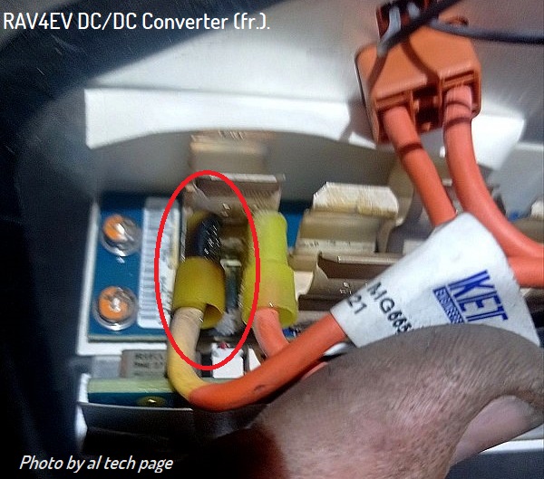
I finished putting back the OBC after replacing the fuses. I think I have connected everything except the cabin coolant hoses. Also, did a coolant purge. I am getting a BMS_f062 - Contactor power supply problem. It is also not going into Ready mode (which was working fine before I started working on it). I have checked the following common reasons:

1. 12V battery is good. Voltage is 13V
2. Put back the HV disconnect
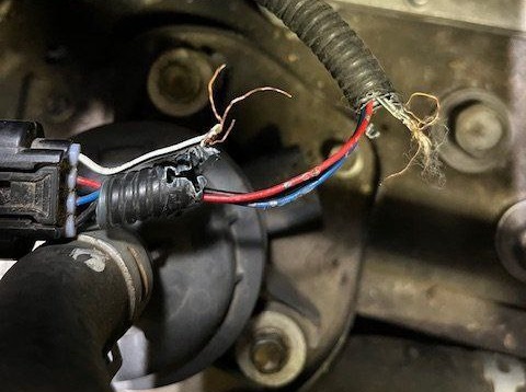
3. I have checked that all connections visible in the picture is snug.


Do you have any theories why this could be happening. Could there be a bad connection in the HVJB?
 

Attachments

  • 1727803194161.png
    1727803194161.png
    96.4 KB
  • 20241001_112818.jpg
    20241001_112818.jpg
    9.7 MB
  • 20241001_112521.jpg
    20241001_112521.jpg
    5.7 MB
  • 20241001_112511.jpg
    20241001_112511.jpg
    5.2 MB
Last edited:
Now back to diagnosing the heater issue
Is there conductivity * on the "minus of HV voltage" line?
Yes. There is continuity at the negative terminals as well.
20240927_155543.jpg

Can you check the heater control signal with an oscilloscope**?
Ordered an oscilloscope which will be delivered in a few days, but a dumb question. How do I tap into the signal to see the pwm waveform going into the heater. If I remove the heater plug, hvil will be broken, if I understand correctly.

When I tested with clamp meter, it showed zero current. Temp and fan was at highest setting when this was measured.
20240913_205104.jpg


After the successful completion of the repair, be sure to repeat the measurements and compare their results with these
It's 2.51M, 2.51M and 241K, very close to the numbers posted in the picture. I will click a pic of this tomorrow and add it here.

@alflash Update: attached the pics. Oddly 2 of the resistances increased from 2.51M to 2.61M. The only difference is I charged the car fully now and the HV disconnect is properly inserted. Not sure if either of this should make a difference.
 

Attachments

  • 20241002_182801.jpg
    20241002_182801.jpg
    1.4 MB
  • 20241002_182718.jpg
    20241002_182718.jpg
    1.4 MB
  • 20241002_182507.jpg
    20241002_182507.jpg
    1.6 MB
Last edited:
Now back to diagnosing the heater issue

Yes. There is continuity at the negative terminals as well.
...
Ordered an oscilloscope which will be delivered in a few days, but a dumb question. How do I tap into the signal to see the pwm waveform going into the heater. If I remove the heater plug, hvil will be broken, if I understand correctly.

When I tested with clamp meter, it showed zero current. Temp and fan was at highest setting when this was measured.
...

It's 2.51M, 2.51M and 241K, very close to the numbers posted in the picture. I will click a pic of this tomorrow and add it here.
Perhaps not the best (not the most civilized) way to connect oscilloscope probes, but simple, proven and without damaging the insulation of the wires
The needle/pin is inserted between the outer insulation of the wire and the rubber seal of this wire at the back of the connector.
Example in this photo.
https://alflash.com.ua/2019/to_rav4ev/connect.jpg
connect.jpg

Hope this will be useful
https://alflash.com.ua/2019/to_rav4ev/cab_heat_w.png
cab_heat_w.png
Note. Connector D15, through which the supply voltage and control signal are supplied, does not have HVIL check contacts.​
 
Last edited:
Tested this today. They seem fine, no short.
Video: https://1drv.ms/v/s!AoMSicNQxi7y5W5Ksgbj23dlFuIT


Checked resistance of all elements. They are seem to be in the same range
Video: https://1drv.ms/v/s!AoMSicNQxi7y5W-G--nP3RXp3aNE

Will test the input signal next after the oscilloscope arrives
then while the oscilloscope is being delivered/on the road, I recommend carefully examining the appearance of the radio components of the control board (attach.4)
https://alflash.com.ua/2019/to_rav4ev/4_board.jpg
4_board.jpg

HTH,

p.s. Unsuccessful attempts at repair by unknown
unknow.jpg
 
Last edited:
...
When I tested with clamp meter, it showed zero current. Temp and fan was at highest setting when this was measured.
View attachment 893 ...
Questions.
  1. Before the current started flowing, was Zero Point Calibration done?
  2. What were the readings on the screen?
    clamp1.jpg
As Reference.
RAV4EV Cabin Heater current at maximum load (with almost 4 kW):
 
Last edited:
Summarizing the results of the tests so far
If the heater fuse is in good condition,
I think based on the continuity that exists between HV terminals and cabin heater terminals, I presume they are in good condition.


if there are no such burns on the connecting contacts (attach.1)
I didn't get the location of this. Is this inside the sealed DC-DC convertor?


if the IGBT transistors are in good condition
Based on the video I posted earlier, no shorts between terminals on any of the transistors

if rats have not chewed through the power wires of the pump of this heater (attach.2)
No sign of damage to the wires.
20241003_170604.jpg20241003_170639.jpg20241003_170700.jpg


if the heating elements are in good condition and not in such a condition
They all appear fine based on the resistance test.


I recommend carefully examining the appearance of the radio components of the control board
I did, couldn't find any visible evidence of damage.

20241003_170328.jpg
Before the current started flowing, was Zero Point Calibration done?
I did not. However, to test if the clamp meter was working, I put the clamp on one of the wires of the 12v battery terminal and it read about ~20A, and after removing I recall that it showed a value that was very close to zero. I can redo the test.

What were the readings on the screen?
Ah ! I forgot to take a screenshot of that. However, I recall doing the math of V*I and it was only about ~200W. I did this test before I drained the coolant from the cabin heater. To re-do the test, I guess I need to connect the hoses back and refill the pink coolant?
 
Summarizing the results of the tests so far
...
Ah ! I forgot to take a screenshot of that. However, I recall doing the math of V*I and it was only about ~200W. I did this test before I drained the coolant from the cabin heater. To re-do the test, I guess I need to connect the hoses back and refill the pink coolant?
There is no need to perform "thermal torture" similar to this :)


You can easily see/determine the current that the heater consumes when turned on by the current surge from the HV battery using the program (video in the previous answer). I assume (IMHO) that turning on a low heating temperature (<25°C) for less than 10 seconds will allow you to see in the program an increase in current from the HV battery when the heating is turned on.

Using, for example, AnyDesk, we can make a joint video of what is happening on the diagnostic program screen and simultaneously under the hood and in the cabin. You film the turning on of the cabin heating with your smartphone, and I record the program screen. This way we will make a video illustration of such a check. :)

Another question. Is the sound of the heating pump working audible when it is turned on?

Note. I am not trying to guess, I am voicing possible reasons and those that I have encountered.
Off. Check your PM.
 
Last edited:
Back
Top