Charging stopped due to system malfunction

Toyota Rav4 EV Forum

Help Support Toyota Rav4 EV Forum:

This site may earn a commission from merchant affiliate links, including eBay, Amazon, and others.
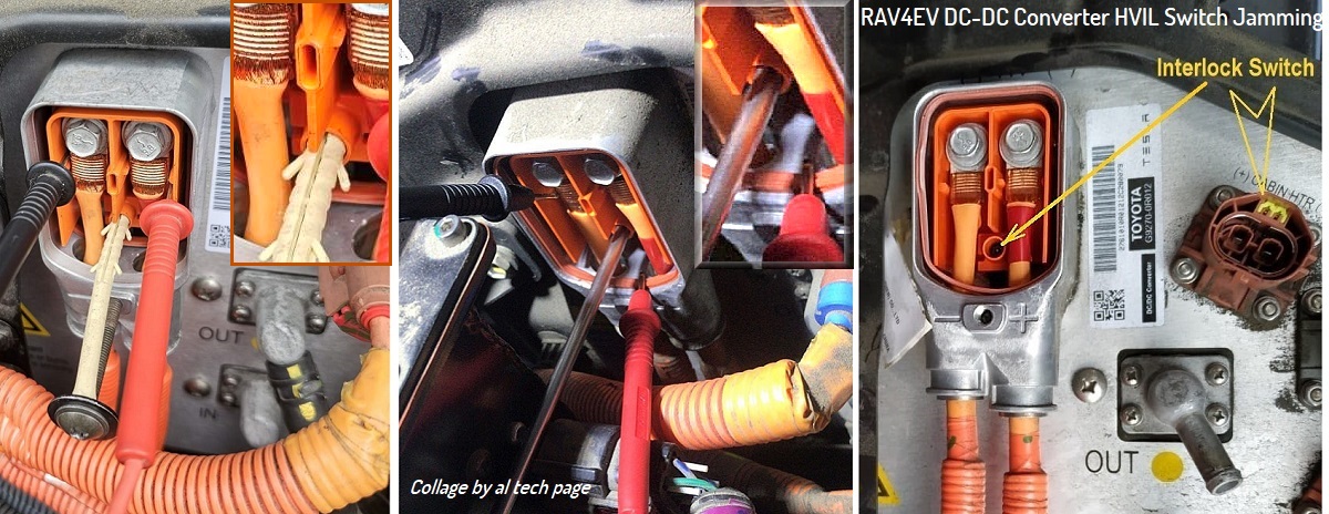
Kind of a dumb question I think. How do I remove the transparent plastic cover to access the HV terminals?

The plastic cover pulls straight out; there's a gasket around the perimeter to make it weather-resistant that also means a little force is required to remove it.

Note that there is an interlock pin molded into the clear cover (about a third of the way up from the bottom). Unless you insert something (non conductive) into the hole in the receptacle to close the switch inside the DC-DC assembly, the BMS will not turn on the contactors and you will get a 'Check EV System' fault displayed.

From your photo, it looks like there are interlock terminals on the other high voltage connectors as well (small terminals adjacent to the high voltage ones). As the interlock system is basically a bunch of closed jumpers in series, having any of these circuits open will keep the contactors from closing.
 
The connectors on the harness for the Cabin Heater, A/C Compressor, and Battery Heater all have jumpers molded into their KET connectors. Disconnect any one of them, and the HVIL (High Voltage InterLock) loop is broken, and the BMS disallows contactors closure.

Vlad recently posted a nice pic of the HVIL interlock on the DC-DC's input cover, over in the THC_d0013 thread.

1726538838163.png

More info on the HVIL system is linked from this post.
 
The connectors on the harness for the Cabin Heater, A/C Compressor, and Battery Heater all have jumpers molded into their KET connectors. Disconnect any one of them, and the HVIL (High Voltage InterLock) loop is broken, and the BMS disallows contactors closure.

Vlad recently posted a nice pic of the HVIL interlock on the DC-DC's input cover, over in the THC_d0013 thread.

View attachment 817

More info on the HVIL system is linked from this post.
+ To this Switch.
https://alflash.com.ua/2019/to_rav4ev/_hvil_switch.jpg
_hvil_switch.jpg


Checking the DC/DC Converter Compressor power supply voltage fuse
https://alflash.com.ua/2019/to_rav4ev/cond_fuse.jpg

+ photo of the one cause of cabin heater malfunction (burnt contact)
https://www.myrav4ev.com/threads/who-still-owns-a-rav4-ev.2572/page-3#post-30305

Another reason for a blown fuse is a broken transistor.
https://alflash.com.ua/2019/to_rav4ev/cabin_heater3.jpg
cabin_heater3.jpg


And this is a test of the cause of the transistor failure.
https://alflash.com.ua/2019/to_rav4ev/cabin_heater1.jpg
Unfortunately, low-skilled technicians only change the transistor, but do not check the resistance of the heating elements.
https://alflash.com.ua/2019/to_rav4ev/cabin_heater1.jpg
cabin_heater1.jpg

The photo shows the check of a serviceable element.
 
Last edited:
Mine did this today as well. One of the pins to the GND is open and the other measures 0 ohms I got lucky and found the 120Vac charger worked as it must be on the good pin lol Not sure if I should worry about the 0ohm reading or if it will go back up with the blown fuse replaced.
Hmm I have fuses coming. But I parked in front of work today for 10min to save time and it was at an EV charger so I plugged in... And I have not changed the fuses yet but it started charging with L2 (30a 208Vac).... I wonder if a contactor welded? And now its freed up? What else would cause this. I measured with a DMM and when it was not charging last week it failed that test.... I will check again today.
 
Arlin, you can't charge with "one good fuse" in the OBC. Whether you're charging with 120v or 240v (or 277v), the same two wires and fuses are in use. If one fuse fails, it's an incomplete path and the OBC will not charge.

Do you have a thread going on your issue? If so, post a screenshot from TPD on your thread (don't post it here, Rakesh has enough going on here).
 
I was knocked out by COVID for about a week, but I am back to working on this.


@asavage I am very close to removing the OBC but got stuck removing the HVJB cover. I think I have removed all the long screws, but there is still something holding it. 20240927_133613.mp4 I was following this. Does this require something to be released from the inside the HVJB box?


Is it possible to check the fuse for the cabin heater?
I checked for continuity and got a beep for continuity between the DC and cabin heater terminals. I tested again after entirely removing the DC/DC and it still had continuity. I think then only the heater is bad and fuse is ok?
 
...I checked for continuity and got a beep for continuity between the DC and cabin heater terminals. I tested again after entirely removing the DC/DC and it still had continuity. I think then only the heater is bad and fuse is ok?
Please show a photo of the measurement showing the location of the probes and the result.
 
I am very close to removing the OBC but got stuck removing the HVJB cover. I think I have removed all the long screws, but there is still something holding it. 20240927_133613.mp4 I was following this. Does this require something to be released from the inside the HVJB box?

I don't remember anything these days, so I can only refer to that thread as you did. To the best of my knowledge, once you remove all the perimeter screws on that cover, you can pull it back just far enough to get a tool inside and release the tab on that black connector, and that will let you swing the whole thing out.

As I mentioned, it's difficult to both pull that aluminum cover to one side, and get a tool inside to release the tab on the black. But there is enough slack in the orange AC input cables.

It's imperative to shift the whole OBC toward driver side in order to gain enough clearance, from memory.
 
Thanks for photo.
Is there conductivity * on the "minus of HV voltage" line?
*

Can you check the heater control signal with an oscilloscope**?
For example, like this


** For example, with this device https://www.amazon.com/dp/B0CMT5WMFY

Update. May be useful/interesting.
Interiors of the heater


Current (resistance) vs. temperature of the heating element of the cabin heater

Note: As you can see from the video, PTC elements are not used in the RAV4EV's main cabin heater.
The PTC heater is used in the Quick Heater and what appears to be the seat heater.
 
Last edited:
@alflash @asavage Update on the charging issue: I removed the OBC and it was indeed a blown fuse. What puzzles me is the fact that the resistance measurements at the charging terminals were OK. In this case, it was the upper fuse that was bad.
 

Attachments

  • 20240928_104339.jpg
    20240928_104339.jpg
    1.5 MB
  • 20240928_104250.jpg
    20240928_104250.jpg
    9.1 MB
@alflash @asavage Update on the charging issue: I removed the OBC and it was indeed a blown fuse. What puzzles me is the fact that the resistance measurements at the charging terminals were OK. In this case, it was the upper fuse that was bad.
Congratulations!
Many thanks for yet another confirmation that statistically there is a very high probability that a blown fuse and this code are "inseparable Siamese twins".
 
Update on the charging issue: I removed the OBC and it was indeed a blown fuse. What puzzles me is the fact that the resistance measurements at the charging terminals were OK.
I can't see a scenario where those two things could exist at the same time. The charge inlet AC pins go directly to those fuses.
 
@alflash @asavage Update on the charging issue: I removed the OBC and it was indeed a blown fuse. What puzzles me is the fact that the resistance measurements at the charging terminals were OK. In this case, it was the upper fuse that was bad.
I suppose it is useful to
1. Read this topic https://www.myrav4ev.com/threads/how-i-fixed-my-rav4-ev-on-board-charger.2537/ and pay attention to this important description of a successful repair https://1drv.ms/b/s!AtSKKmN-5msBg_oYXNH9E1vYZ_8bDA.​
3. After the successful completion of the repair, be sure to repeat the measurements and compare their results with these https://www.myrav4ev.com/threads/charging-stopped-due-to-system-malfunction.2692/#post-31688
 
Last edited:
I can't see a scenario where those two things could exist at the same time. The charge inlet AC pins go directly to those fuses.
Can you show a wiring diagram of the AC input connections to these fuses and the connections of the other sides of the fuses to other components for the Tesla onboard charger? I am especially interested in whether the AC wire pins are connected to other electrical components other than the fuses?

Update. As I understand this your photo
https://asavage.dyndns.org/Toyota/RAV4/EV/Charger-Onboard/Tesla_Model_S_GEN1_OBC_032b.jpg

AC voltage wires are shunted with paper or ceramic HV capacitor(s) with a capacity of 0.47 μF.
 
Last edited:
Can you show a wiring diagram of the AC input connections to these fuses and the connections of the other sides of the fuses to other components for the Tesla onboard charger? I am especially interested in whether the AC wire pins are connected to other electrical components other than the fuses?

Update. As I understand this your photo
https://asavage.dyndns.org/Toyota/RAV4/EV/Charger-Onboard/Tesla_Model_S_GEN1_OBC_032b.jpg

AC voltage wires are shunted with paper or ceramic HV capacitor(s) with a capacity of 0.47 μF.
Oh . . . the light comes on. (Matt, you led me astray :LOL: ) Yes, I've been giving out bad advice on this "test", haven't I?

Contactor. It looks like the fuses feed that DPST contactor, so . . . no load difference when testing at the charge inlet, between a good fuse and a bad one. It's even my diagram. Man, am I sorry I missed that. Thanks, Vlad.

---

I've made a request to allow adding a note to my May2023 post about this bogus test I posted.
 
Last edited:
Oh . . . the light comes on. (Matt, you led me astray :LOL: ) Yes, I've been giving out bad advice on this "test", haven't I?

Contactor. It looks like the fuses feed that DPST contactor, so . . . no load difference when testing at the charge inlet, between a good fuse and a bad one. It's even my diagram. Man, am I sorry I missed that. Thanks, Vlad.

---

I've made a request to allow adding a note to my May2023 post about this bogus test I posted.
"One swallow does not make a spring" (proverb).​

Apparently, we need to get confirmation of your conclusion with an opportunity, i.e. during the same check in another car with the code CHG_f078.
Unfortunately, we do not have documentary results (photos) of the check. Yes, Rakesh Suresh measured everything correctly - no doubt! But I would like to see it with my eyes :).

Therefore, I suggest that for now both options are considered only "versions" ...

Update.
If it's not too much trouble, please let me know if the AC input voltage is connected only to the fuses and (presumably) to the input capacitor as seen in this yours photo?
Tesla_Model_S_GEN1_OBC_032b.jpg

dfergenson.jpg
Or are other components connected as well?
 
Last edited:
Back
Top