Charging: Stopped by System Malfunction

Toyota Rav4 EV Forum

Help Support Toyota Rav4 EV Forum:

This site may earn a commission from merchant affiliate links, including eBay, Amazon, and others.
View attachment 1317

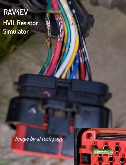
On the OBC's Logic connector, where you were testing before, pick one terminal and use it for one of your ohmmeter's leads. For the other lead, backprobe that external jumper (either terminal: they're shorted together). Your ohmmeter should read either 0Ω, 60Ω, or OL.

  • If it reads 0 (or under 1, anyway), the lid switch circuit is OK; look at the resistor side of the circuit
  • If it reads 60 (or thereabouts), the resistor side of the circuit is OK; look at the lid switch side
  • If it reads OL, move your ohmmeter lead on the Logic connector to the other terminal and try again (ie if you were connected to pin 3, try pin 9 now)

Just measured now:
- From OBC X042 Pin #3 to J5 : OL (open circuit, no resistance of 60Ω, something is fishy)
- From OBC X042 Pin #9 to J5 : ~7.1Ω (fluctuating)
- ON OBC X042 across 3 & 9 : OL

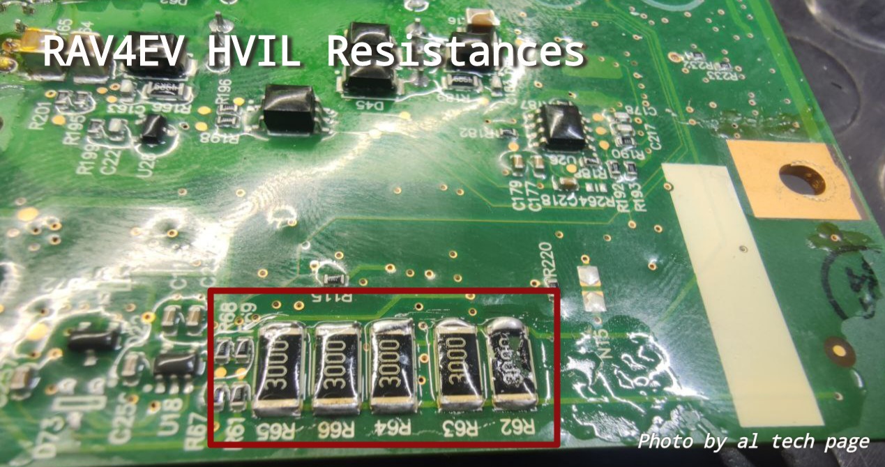
I'm taking out the OBC and looking inside (for the 60Ω resistor).
Is OBC repairable, or, should I look for another one? I'd at list give it a try.. Just dunno where to look🥸
 
If there is available access to the charger "brains" board, need inspect it with a magnifying lens and check the resistance of the HVIL resistor line with an ohmmeter: 300 Ohm x 5 (the appearance ща R62 ÷ R66 was shown earlier).
And check their conductivity with the ILKO and ILKI contacts of the D4 connector.

Off-topic.
View attachment 1315

I thought that this has no resistor (it's a jumper only). Do you know?
Sir, please let me know who and where claimed that this board has HVIL resistor(s).
Thanks in advance.
.
 
Last edited:
If there is available access to the charger "brains" board, need inspect it with a magnifying lens and check the resistance of the HVIL resistor line with an ohmmeter: 300 Ohm x 5 (the appearance ща R62 ÷ R66 was shown earlier).
And check their conductivity with the ILKO and ILKI contacts of the D4 connector.

All resistors show 60Ω. However, R65 (leftmost in the pic) hesitates between 59.9Ω - 60Ω

There's conductivity for both pins #9 & #3 from D4 (X042) to J4 harness as shown in pic.
 

Attachments

  • MB_Resistors.jpeg
    MB_Resistors.jpeg
    239.2 KB
  • D4_Connector.jpeg
    D4_Connector.jpeg
    155.9 KB
...
And check their conductivity with the ILKO and ILKI contacts of the D4 connector.
...
1. Sir, each of the resistors shown in the photo has a resistance of 300 Ohm.
2. It's a pity that the recommended conductivity check between this "group" resistance and the ILKO(#3) and ILKI(#9) pins of the D4 connector has not been done...
3. Apparently, I'm superfluous in this topic...
 
Last edited:
1. Sir, each of the resistors shown in the photo has a resistance of 300 Ohm.
2. It's a pity that the recommended conductivity check between this "group" resistance and the ILKO(#3) and ILKI(#9) pins of the D4 connector has not been done...
3. Apparently, I'm superfluous in this topic...

It's not you, it's me; I misunderstood (again) your point.

From ILKO(#3) , all the resistors show 60.2Ω (not 300Ω) !

From ILKI(#9) , all resistors show OL
 
It's not you, it's me; I misunderstood (again) your point.

From ILKO(#3) , all the resistors show 60.2Ω (not 300Ω) !

From ILKI(#9) , all resistors show OL
1. Wiring/track on the printed circuit board/metalized hole(s) on the board/contact of the board connector between one side of the "group" resistor and the D4 connector is openю
2. Sir, those five resistors (300 Ohm*) are connected in parallel** and therefore their total resistance is 60 Ohm!

https://alflash.com.ua/2019/to_rav4ev/ching3.jpg
ching3.jpg

* For example, take a look SMD Resistor Code Calculator
https://www.digikey.com/en/resources/conversion-calculators/conversion-calculator-smd-resistor-code

**
par.png
 
Last edited:
1. Wiring/track on the printed circuit board/metalized hole(s) on the board/contact of the board connector between one side of the "group" resistor and the D4 connector is openю
2. Sir, those five resistors (300 Ohm) are connected in parallel* and therefore their total resistance is 60 Ohm!

Now it makes sense. I must have missed that they were in parallel. I thought each individual resistor should measure 300Ω, which is not possible as soldered.

Since I can read the famous 60Ω from pin #3 to the resistor pack, but not from pin #3 to J5; the circuit must have been broken somewhere, as you said.

I don't see any darkened color components on the board. Could be an internally detached component, a resistor, a diode, or something. The clear protective coat makes checking components very hard.

Beyond this, it exceeds my abilities. I think I better get another OBC.
Any other components that I need to check/worry/replace?

BTW, hokiematt mentioned swapping the MB to eliminate resetting the new Tesla OBC. But, where is the EPROM that the SW flashes located? If it is on the MB, then swapping would not be a good idea?
 
If it's just the HVIL, it should be very repairable, you just have to fix the loop so it's connected through. You don't have to repair the board, just bodge a wire to replace the broken circuit. If you can find someone who can solder a wire, you should be able to repair it. For testing purposes, you might even be able to use a clip lead to bridge the gap.
 
Last edited:
Back
Top