Additional Battery Project - Possible Extra 40 kwh

Toyota Rav4 EV Forum

Help Support Toyota Rav4 EV Forum:

This site may earn a commission from merchant affiliate links, including eBay, Amazon, and others.
jimbo69ny said:
Battery Plans:
I plan on using brand new lithium ion LG MJ1 18650 battery cells. Each cell is rated at 3500 mah and 10 amps constant. Here they are, https://liionwholesale.com/products...at-top-wholesale-discount?variant=11564550916
I can fit 9 modules in a vertical formation in the lower cargo area if I cut out the floor pan. I plan on matching the OEM pack to keep voltage the same. The OEM pack is 92s48p, I am planning on building a 92s32p pack. I can fit 320 cells in each module, 2,944 total cells in this configuration. The floor of the cargo area will be raised about 2 inches.

How are you going to connect all the batteries in series/parallel ? electrically spoken.
Why did you put both a contactor and manual switch in series ?
Would a simple manual switch in series with the coil of the contactor be enough to prevent the batteries to be paralleled ?
There is a lot of high voltage/high current now going over a lot of contacts that each introduce some milli-ohms in resistance.
 
fromport said:
jimbo69ny said:
Battery Plans:
I plan on using brand new lithium ion LG MJ1 18650 battery cells. Each cell is rated at 3500 mah and 10 amps constant. Here they are, https://liionwholesale.com/products...at-top-wholesale-discount?variant=11564550916
I can fit 9 modules in a vertical formation in the lower cargo area if I cut out the floor pan. I plan on matching the OEM pack to keep voltage the same. The OEM pack is 92s48p, I am planning on building a 92s32p pack. I can fit 320 cells in each module, 2,944 total cells in this configuration. The floor of the cargo area will be raised about 2 inches.

How are you going to connect all the batteries in series/parallel ? electrically spoken.
Why did you put both a contactor and manual switch in series ?
Would a simple manual switch in series with the coil of the contactor be enough to prevent the batteries to be paralleled ?
There is a lot of high voltage/high current now going over a lot of contacts that each introduce some milli-ohms in resistance.

Hello Fromport,

I am going to use bus bars made of bare copper wire. Probably 3 - 14 gauge wires twisted together. I am going to then fuse each cell independently just like Tesla does. Info on the method can easily be find on youtube and I think I posted a video in my original post.
I am trying to build it as safely as possible. I am going to have temperature sensors, an inertia switch and a manual kill switch on the dash that will all kill the contactors and break connection with the car. The maintenance switch is there as another level of protection. I can also flip the maintenance switch off killing power from the secondary battery to the contactors then disconnecting the pack at the contactors if i want to remove the entire pack. Removing the entire pack would be a 5 minute job with a engine hoist.
I am not worried about the resistance. If anything I NEED the resistance. The OEM pack is going to have a higher resistance than the new pack because of its age and use. That means that the newer pack will be supplying more of the power needed to run the car. If your theory is true and my 2 connections are adding resistance, that is fine with me.
 
jimbo69ny said:
Hello Fromport,

I am going to use bus bars made of bare copper wire. Probably 3 - 14 gauge wires twisted together. I am going to then fuse each cell independently just like Tesla does. Info on the method can easily be find on youtube and I think I posted a video in my original post.
I am trying to build it as safely as possible. I am going to have temperature sensors, an inertia switch and a manual kill switch on the dash that will all kill the contactors and break connection with the car. The maintenance switch is there as another level of protection. I can also flip the maintenance switch off killing power from the secondary battery to the contactors then disconnecting the pack at the contactors if i want to remove the entire pack. Removing the entire pack would be a 5 minute job with a engine hoist.
I am not worried about the resistance. If anything I NEED the resistance. The OEM pack is going to have a higher resistance than the new pack because of its age and use. That means that the newer pack will be supplying more of the power needed to run the car. If your theory is true and my 2 connections are adding resistance, that is fine with me.

You have read this on the spec sheet ? :
5.2 Prohibitions
Do not use with other batteries or cells.
Do not solder on battery directly.
Do not use old and new cells together for packing.
I am certainly not an expert but paralleling smaller wires to make a larger wire is imo never a good idea.
Unless you control the milliohm resistance , one wire could carry more current, warm up , burn through and then the other will follow. especially with DC you really don't want to create arcs. It is so different from AC.
If you really put 31 parallel and each cell can draw 10 amps (datasheet) you are talking about 310 amps.
You will need larger than 4/0 cables to carry that much current. see http://www.cerrowire.com/ampacity-charts
 
Yes, I know paralleling two different cells is not recommended by some in the electronics world but it works and I haven't seen any negative results. The only result is that some cells will see a higher or lower amperage based on the resistance of the cells. I dont see the problem there as long as you plan for it. Others have added packs to their EVs and it works. Others have even used different chemistry cells and it still works. I am using the same series configuration of 18650 cells (92). The only difference is that they are brand new and higher mah. I haven't seen any proof that anything bad will happen.

The cells in the new pack are not going to see 10 amps each. Will never happen. And if somehow it does, there is a 250 amp fuse under the hood and another one in the rear in addition to the 8 amp fuse wires that will be on each cell.
The main pack has a 350 amp fuse so lets use that number as an example. If I have 350 amps flowing to the motor those amps will be divided between the 48 parallel cells in the OEM pack AND the 32 cells (I might go to 33) in the secondary pack. That's 80 cells in parallel. 350 / 80 is 4.3 amps per cell. Then, back to the resistance.. The new pack will have lower resistance so the cells in the newer pack will deliver slightly more power than the cells in the OEM pack. I dont know how much but I highly doubt it will be more than 7.81 amps per cell (250 amp fuse / 32 cells = 7.81 amps per cell).

As for the wire, I used really nice wire that was designed for EVs. It has a higher amperage rating than any other type of cable. I went with 2 gauge and it is rated up to 255 amps. Here is the spec sheet. http://evwest.com/support/Shielded_Battery-Irradiated_XLE.pdf
I spoke with Valory (he added Calb batteries to his Rav EV a long time ago) and he told me he never saw over 200 amps going from his secondary pack. I think I am going to be fine. But just in case, everything is fused.

As for arcing read my previous posts. I posted a screenshot and a link to a video in which Jack from EVTV connected 2 Tesla 85kw battery packs in parallel. Both at very different SOC. I forget exactly but as long as they are within something like 60% SOC they will balance just fine. They dont have to even be close. Read the post and watch the video, its interesting.
 
jimbo69ny said:
So you think that the 12 volt power going to the board of the shunt is going to somehow cause issues with the 12v system in the car? Ive seen other people using this monitor and havent heard that before.

I do have fuses. I have one under the hood where I get power from the Jdemo and a second one at the additional battery maintenance switch. Ill post photos when I get it done. Its snowing like crazy and I have a newborn at home but Ill try to get outside to do it today. I usually end up working late at night when mom and the kid go to bed around 8.

Yes, I do if you are using the car's charging system to charge your auxillary pack (at least in my experience, I have the same ammeter).

I was referring to the small gauge wire running to the volt meter on the ammeter as it has access to all the current available from the pack and would vaporize in an instant if it ever shorted to the negative terminal close by or within the ammeter.

I understand, all the more reason to be careful! :)

BTW, do you plan on energizing the system manually when you get in the car or do you have something else in mind?
 
ph2 said:
jimbo69ny said:
So you think that the 12 volt power going to the board of the shunt is going to somehow cause issues with the 12v system in the car? Ive seen other people using this monitor and havent heard that before.

I do have fuses. I have one under the hood where I get power from the Jdemo and a second one at the additional battery maintenance switch. Ill post photos when I get it done. Its snowing like crazy and I have a newborn at home but Ill try to get outside to do it today. I usually end up working late at night when mom and the kid go to bed around 8.

Yes, I do if you are using the car's charging system to charge your auxillary pack (at least in my experience, I have the same ammeter).

I was referring to the small gauge wire running to the volt meter on the ammeter as it has access to all the current available from the pack and would vaporize in an instant if it ever shorted to the negative terminal close by or within the ammeter.

I understand, all the more reason to be careful! :)

BTW, do you plan on energizing the system manually when you get in the car or do you have something else in mind?

Thanks for the pointer. The part you suggested isnt very expensive and would be easy to add.

You just touched on the thing I am working on now. The OEM contactors operate on CAN, which is not my forte. So I need to find another way to trigger my contactors. I am planning on going under the hood and testing wires until I find one that mimics a contactor signal. I am looking for either a ground signal or a power signal between 10 and 30 volts that changes when 1. j1772 is plugged in and car begins to charge. 2. when vehicle is remote started and car powers up. 3. When car is started manually and driven. In all 3 of those situations the OEM contactors close. I'd want my contactors to also close.

I asked Tony for help but he said he didn't know.
 
davewill said:
Any reason you can't buy and build one or two modules initially? It might take some of the sting away if you have to deal with problems.
In order to be of much value for Jim's implementation, you would have to build a smaller 92S pack to test with, like maybe 92S4P. That is 1/8 the size, but if it did turn out well, you would probably have to tear it down and reconfigure it for the final pack size.

Probably the most difficult thing I've heard in Jim's plan is the cell-level fusing. Wire bonding is not trivial and rather difficult to do without proper equipment.
 
miimura said:
davewill said:
Any reason you can't buy and build one or two modules initially? It might take some of the sting away if you have to deal with problems.
In order to be of much value for Jim's implementation, you would have to build a smaller 92S pack to test with, like maybe 92S4P. That is 1/8 the size, but if it did turn out well, you would probably have to tear it down and reconfigure it for the final pack size.

Probably the most difficult thing I've heard in Jim's plan is the cell-level fusing. Wire bonding is not trivial and rather difficult to do without proper equipment.

As miimura said, it wouldnt really work unless I made a mini pack. It has to be 92s which is almost $500 in cells. Building one module wouldnt work because each module is only 10s.

Yeah the cell level fusing is going to be tedious. I just ordered a spot welder to do the job though so that will help. Some people online solder. That would be a TON OF WORK!!! Not to mention it heats up the cell. You cant prove that heat is harmful but generally speaking heating a Li-on cell is no bueno.
 
Possible issue. I’m not sure what’s going on yet. Car is behaving strangely and doesn’t want to be charged. It all started when I let the battery drain to about 300 V. I wanted to see how low it would go before the car shut off. The climate control limited warning came up and I stopped the test. That was around 297 V.

During that time I also unplugged a couple harnesses under the hood to get a better look at them. The car was off. I just wanted to look at them closer to see how easily I can get a meter lead to the wire.

After that I had the check EV system warning. I cycled the power on and off five times and it went away but it wouldn’t except a charge. So I disconnected the battery for about 15 minutes. It still wouldn’t except a charge with my openEVSE charger. Warning light came back on. So I cycled on and off 5 times again and disconnected the battery for another 15 mins. I finally got the car to except a charge using the OEM charger. I let that go until there was a bar then plugged in my openEVSE charger again. It took a charge and is now about 3/4 full.

I just went out to see what was going on. It was still charging. I turned on the ignition to check the voltage using my meter and it immediately stopped charging and gave me a check ev warning light. The warning light goes away after I cycle on and off three times. But is soon as I connect either charger it gives me a charging error and the check ev message.

The only thing connected to the car are the two cables going to the OEM battery. They connect to my new contactors. The negative leg goes to the shunt but that’s it. I’m going to reset the battery again to see what happens.

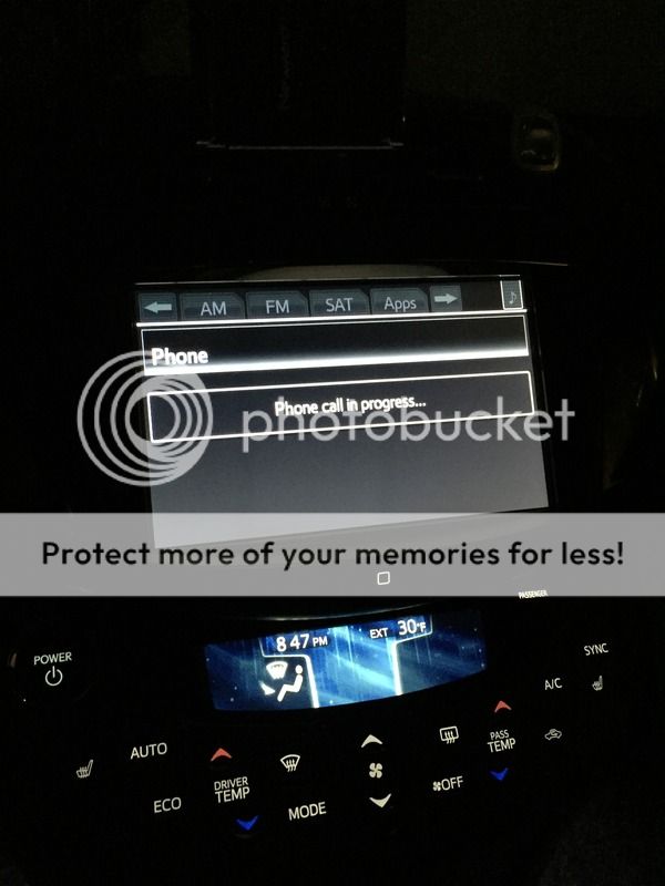
On a related note, I noticed today that my radio continually connected to my phone like my phone is making a phone call. One time my phone was inside the house. I am wondering if the radio frequency coming from the shunt/meter to the meter display is messing with my car for some reason. I’m going to disconnect it tonight to see what happens
 
I left the 12v battery disconnected for about over an hour. Just reconnected it, car rebooted, car started, car is now charging.

However, something strange is going on. Again when I started my car the radio wouldn't work. The radio said that I was making a phone call. I was not, I took a photo of the screen and I heard the camera noise through my cars speakers. I closed all of the apps on my phone, tapped the end call button on my steering wheel, hit the radio button and for some reason it went back to normal and started playing pandora. My shunt did not have power (it transmits data to the display) but my meter display did have power. Later Ill go outside and try to recreate everything except Ill leave the meter display without power. I did disconnect power to the display while the call issue was happening. Even though the display was powered down the car still thought I was on a call.

Not sure whats going on yet but the car IS charging and operating normally, other than all the phone calls it thinks I am making....

Here is the meter that I have in the car. https://www.ebay.com/itm/400V-300A-...e=STRK:MEBIDX:IT&_trksid=p2057872.m2749.l2649

DA09074E-5FAD-4865-A24C-224D260D3B3D_zpsubamizdo.jpg
 
Ok, just went out again. Car was charging and operating fine.

Before I opened a door I shut down my iPhone 6. Totally off. Got in the car and pressed power with the car charging AND the display still powered. Shunt/transmitter off. NO phone calls were being made. Good

I went to the back and engaged the contactors. Car immediately stops charging and will not restart. I had the check ev system message but it again went away after THREE power cycles.

I unplugged the 12v 5 amp fuse for the contactors but the car still wouldn’t charge. So I disconnected the 12v battery again and it is sitting like that now.

While the 12v battery is disconnected I am now going to disconnect the shunt and see what happens when I do all of this all over again. We’re of course getting more snow as I do all of this. Winter needs to end!
 
Update: Working through the snowstorm...
I reconnected the 12v battery, display connected, phone on, shunt disconnected from the ground HV battery wire and not powered up by 12 volts.

Car starts and charges like normal. NO PHONE CALL being made!

I go into the back and send 12 volts to the contactors. Car does NOT stop charging! Continues working like normal!

At this point I have to say that the Chinese meter/shunt is doing something weird. The display is fine, its something in the shunt/meter. It messes with the car so it thinks there is a phone call happening, not the end of the world because if I push enough buttons it goes away. But being connected while attempting to charge does something to the car and sends it into error mode. An error that will only go away by disconnecting the battery then cycling power THREE times. Why it is 3 and not 5 like normal, I dont know.

As long as I am NOT charging the car operates fine with the shunt connected, aside from the phone call happening when I power up the car. I drove the car around today with the shunt/meter connected and it transmitted the HV battery voltage to the display without any problems. The issues only came up as I tried to charge it.

Conclusion, I am still a go on this project. The new battery BMS will come with its own shunt so I will remove this Chinese shunt. HOPEFULLY the Orion or Batrium shunt doesnt have the same issue. If it does, I guess I wont be metering current... The fact that the car operates fine and charges without the shunt connected gives me hope. Val told me that the onboard charger charged both batteries when he did his set up. It should work for me too.
 
Try disconnecting the voltage lead and 12v on your shunt... sounds like that isolation issue I was referring to... IIRC it only surfaces during charging.
 
Yep, saw your update post too late... should work fine if you install the 12v - 12v dc isolation converter I mentioned earlier, most will likely need this.
 
Every EV drive I've worked with has some sort of ground current leakage detection circuit that monitors if there is any potential for current to flow between the HV battery pack and chassis ground. On our Ravs it's expressed as 'isolation resistance', and should typically be >2 Mohms. The intent is that if you were to accidentally come in contact with one of the HV leads and chassis ground at the same time, the current wouldn't be enough to kill you. The threshold for setting a fault is usually in the range of a milliamp or so.

In this case, using a shunt wired to a HV lead in a meter that is also tied to the vehicle ground resulted in some leakage current, that in turn caused a drop in the calculated isolation resistance and thus an EV system warning.

As suggsted, an isolated DC-DC converter will normally fix this problem. Note that all converters are not the same, and many have a common ground between input and output. To solve this problem, only an *isolated* converter will do.

Alternatively, my preferred solution is a LEM current sensor: non-contact and complete isolation from the circuit it is measuring. These are available in a wide variety of sensing ranges and cable pass-throughs. There is a dual range LEM used in the Chevy Volt battery packs.
 
ph2 said:
Yep, saw your update post too late... should work fine if you install the 12v - 12v dc isolation converter I mentioned earlier, most will likely need this.


Thank you. I’m not sure I’m going to keep this display so I’ll hold off on buying the part for now.

I just got the quote for the box from the welder..... 1/4” aluminum isn’t cheap..... $1000!! And that doesn’t include cutting the floor and putting in a new floor pan, that’s just the box. I’ve decided to go with high strength S2 fiberglass.
 
Update:
Since receiving a quote for an aluminum box that was way higher than I expected, I have totally redesigned my box and modules. The new design will be actually be easier and cheaper but I will lose more space in my car. I have decided to go with fiberglass for the shell of the box and GPO-3 to make up the 3 levels inside of the box. The fiberglass is a super strong S-2 Glass type. In many of its specs it is actually better than carbon fiber, Kevlar, and steel.
This is the glass I purchased. https://www.tapplastics.com/product/fiberglass/fiberglass_fabrics/s_2_glass_4522/88
The resin is a high strength polyester. Here is a link to that. https://www.tapplastics.com/product..._resins/tap_isophthalic_high_strength_resin/9
The GPO-3 is a fire resistant, non conductive material that is also super strong. Here is a link to that. https://www.electro-wind.com/rochling-glastic-gpo3-utr-1494-red-1-4x48x96.html
All of the items will make the box stronger than steel but a quarter of the weight. All said and done I will save about $800 on the box/body work and my car will remain original (no cuts or modifications)

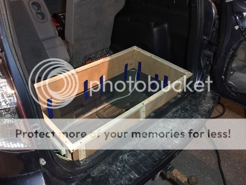
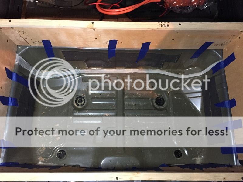
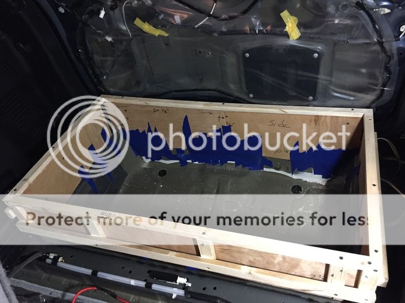
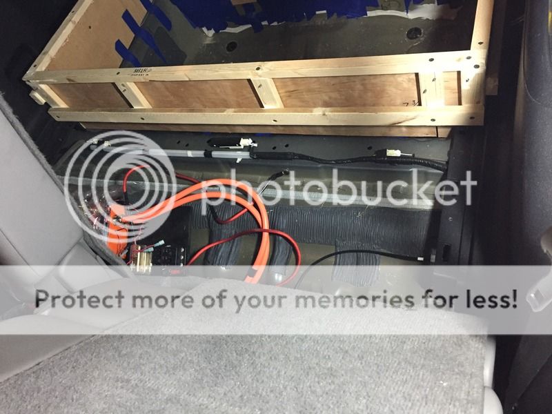
This shows the height and frame of the new box. Just getting started to prep for fiberglass
3EB7B8E9-F37D-4A8C-ADA3-53F34ACFF4BC_zpsq0il3wm5.jpg


EE520889-4162-4659-A5E1-62FBA6169F60_zpsxtb660kq.jpg


9F991695-4076-4827-BD44-264FED55819D_zpsejacfips.jpg


This was a bit disappointing... The lip of the box touched the back door so when the back door closed it pushed the frame inward. That changed the alignment of the box which made it not work. So I am going to have to cut the lower part of my rear door panel off and fiberglass a new piece on. The plastic panel is common enough that I can get a replacement later if I need to.
9AB1F898-5334-4686-85C6-40BD79AA79A3_zps6hkhvlrk.jpg


I have all of this space for the BMS and/or more batteries later down the road.
763CB698-897C-43F4-9F39-072692C73B08_zpsp0dsimfe.jpg


This is what the new modules are going to look like. I am going to have 4 of these modules on each level. I only have 3 pictured because I am out of the cell holders currently.
1587EBA6-78EF-495D-9AC6-EB353ACE22FC_zpsfl9w1mwl.jpg


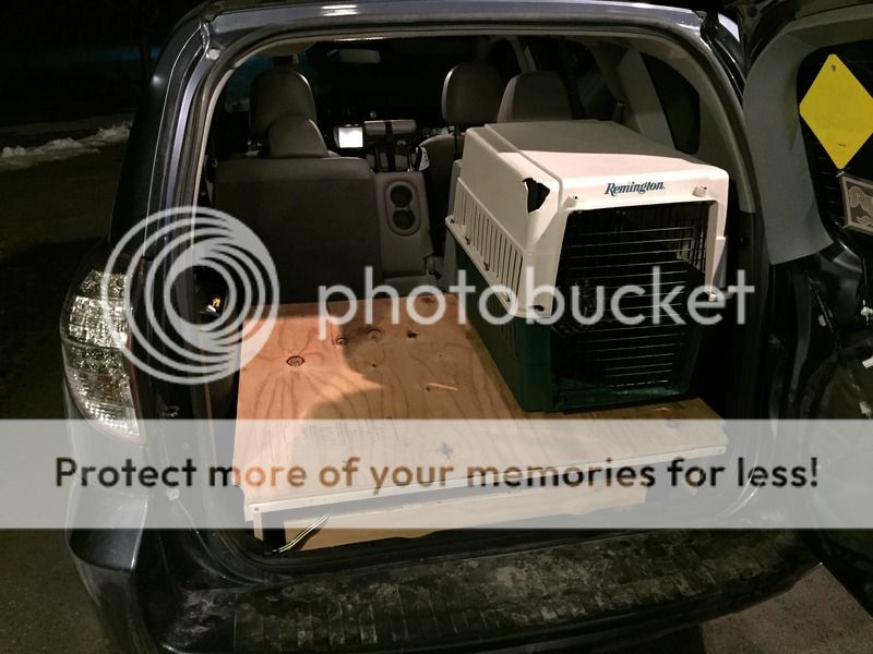
This shows what the new height will be. My car compared to my wifes car.
65F09123-CC1B-4133-B016-9323CCA75173_zpsynqixwcw.jpg

D3CE32B0-D021-437D-BBAE-159C58D4373C_zpsgjz9je8i.jpg
 
I thought I should post an update. I havent in a bit.

I currently have 3 projects that I have been working on. I had to finally focus on one because they are each pretty expensive endeavors. Here are my 3 projects.
1. As this thread shows, I want to add an additional battery pack to my Rav. Unless more suitable batteries fall into my lap, I am going to use 18650 cells and put them together into modules. I found two suppliers. I can get recycled cells that are 2000-2800 mah for a $1 each, or $3,680. OR 3500 mah LG MJ1 cells for $3.80 each. Its a great deal but it would take 2-3 months for them to be shipped overseas. The total would be about $14,000! Its a lot of capacity but thats a lot of money.

2. I want to build a range extending battery trailer. As you might have seen on facebook, I found a working Rav pack. With the help of Matt, another member here, we are going to build a controller for it. He is fluent in CAN BUS which I am not. He has made a lot of progress already. We should have a controller soon. Everything else is ready. I have all of the connections, wire and trailer. For that reason I decided to complete project 2 first. I am basically there.

2 1/2. Currently the range extending trailer R.E.T. will be made using the Rav pack. However I am keeping my eyes open for a Tesla 85 or 100 kw pack. I hope to do the same thing but with a Tesla pack. Potentially tripling my range!

2 3/4. Once I get a Tesla R.E.T. I have a long term goal of building a teardrop trailer that I can bolt on and off as needed. My wife and I love road trips and I really like the idea of pulling a small camper for a long road trip. I plan on building everything as lightweight as possible. Aluminum frame trailer, fiberglass teardrop shell, aluminum teardrop frame and as few as amenities as the wife will tolerate.

3. I figure if someone at some point wants to buy my Rav4 EV modules, I will keep the battery shell and stuff it full of 100kw Tesla modules. I took apart the pack and measured everything. I can fit 15 Tesla 100kw modules. That would be 90s instead of our 92s but it might be ok. Again, because I dont speak CAN I would have to rely on help from others. I am trying to learn but it just isnt my thing. Not to mention that it requires some pretty expensive equipment to dive in and test with. Regardless, if I can get help, I can make 15 modules fit. I just dont know what the Tesla and Toyota components would do when it saw power coming from a different pack. No idea. Also worth noting, it would require a 3 inch spacer in order to make room for a third level of modules. Currently the pack has 2 levels. It would mean that the pack would sit lower, closer to the ground. I dont think that in and of itself is an issue but I would probably want to make a couple fiberglass aero panels to fix aerodynamics under the car.

So thats where I am at now. Trailer is almost done and I am keeping an eye out for a Tesla pack. I just finished the fiberglass onboard battery box so that is still progressing too. I have to go put my kid to bed but Ill try to get some photos up tonight. In the meantime, you can check out my youtube page. Warning though, it sucks and I'm sure I sound like an *****. haha https://www.youtube.com/user/jimbo69ny
 
Back
Top